Reaction plate adaptor apparatus

a technology of adaptor apparatus and reaction plate, which is applied in the direction of mixers, household objects, combustion processes, etc., can solve the problems of skin burns or providing an ignition source, particularly hazardous nuke flame of bunsen burner, and a number of significant hazards of oil baths, etc., and achieves efficient heat transfer

Inactive Publication Date: 2006-09-07
ASYNT
View PDF4 Cites 13 Cited by
  • Summary
  • Abstract
  • Description
  • Claims
  • Application Information

AI Technical Summary

Benefits of technology

[0012] As the recess, the insert and hence the reaction vessel are aligned centrally with respect to the heating plate an enhanced heating effect is achieved over similar known devices in which the reaction vessels are positioned off centre. Additionally, effective stirring of the reaction medium is also possible, particularly where viscous liquids are used due to this centralised location of the reaction vessel within the magnetic field generated over the reaction plate.
[0020] Preferably, the device comprises location means provided at said base unit capable of seating said base unit in position at the reaction plate. The location means is capable of inhibiting lateral displacement of the device relative to the stirrer hotplate.
[0023] The base unit and insert of the present invention may be made of any chemically resistant material including for example a polymer based compound, a metal, in particular aluminium or a metal alloy, in particular stainless steel. Additionally, the material of the present invention is chosen to provide efficient heat transfer from the reaction plate to the reaction vessel.

Problems solved by technology

When used within a laboratory environment, the naked flame of the bunsen burner is particularly hazardous as it may serve as an ignition source for flammable solids, liquids or vapour.
Oil baths pose a number of significant hazards.
Firstly, the viscosity of the oil decreases when heated and spillage or splattering of the heated oil commonly results in skin burns or provides an ignition source.
However, one of the more frequent accidents associated with oil baths stems from overheating of the oil resulting in ignition or explosion.
When used in combination with an oil bath, the significant risks posed to laboratory personnel remerge.
Where a liquid / oil bath is not used the limited surface contact area between the planar hotplate and the curved flask provides for inefficient heat transfer and a limited heating effect.
This may be a particular problem where the reaction medium is particularly viscous.

Method used


Image

  • Reaction plate adaptor apparatus
  • Reaction plate adaptor apparatus
  • Reaction plate adaptor apparatus

Examples


Embodiment Construction

[0045] There will now be described by way of example a specific mode contemplated by the inventors. In the following description numerous specific details are set forth in order to provide a thorough understanding. It will be apparent however, to one skilled in the art, that the present invention may be practiced without limitation to these specific details. In other instances, well known methods and structures have not been described in detail so as not to unnecessarily obscure the description.

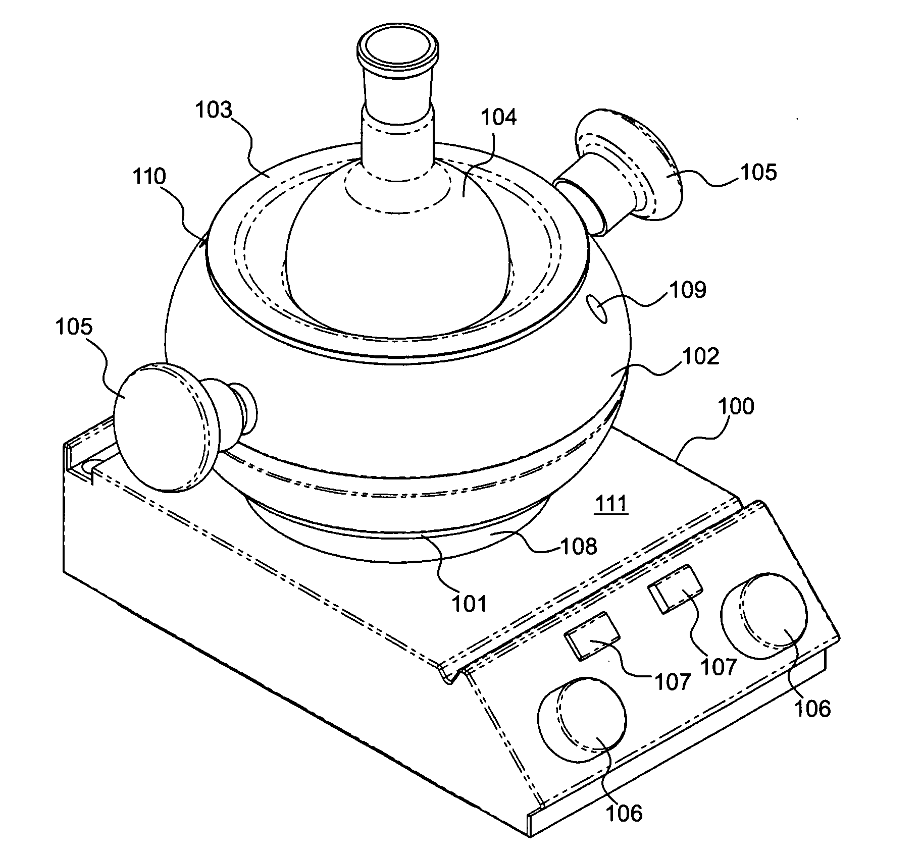
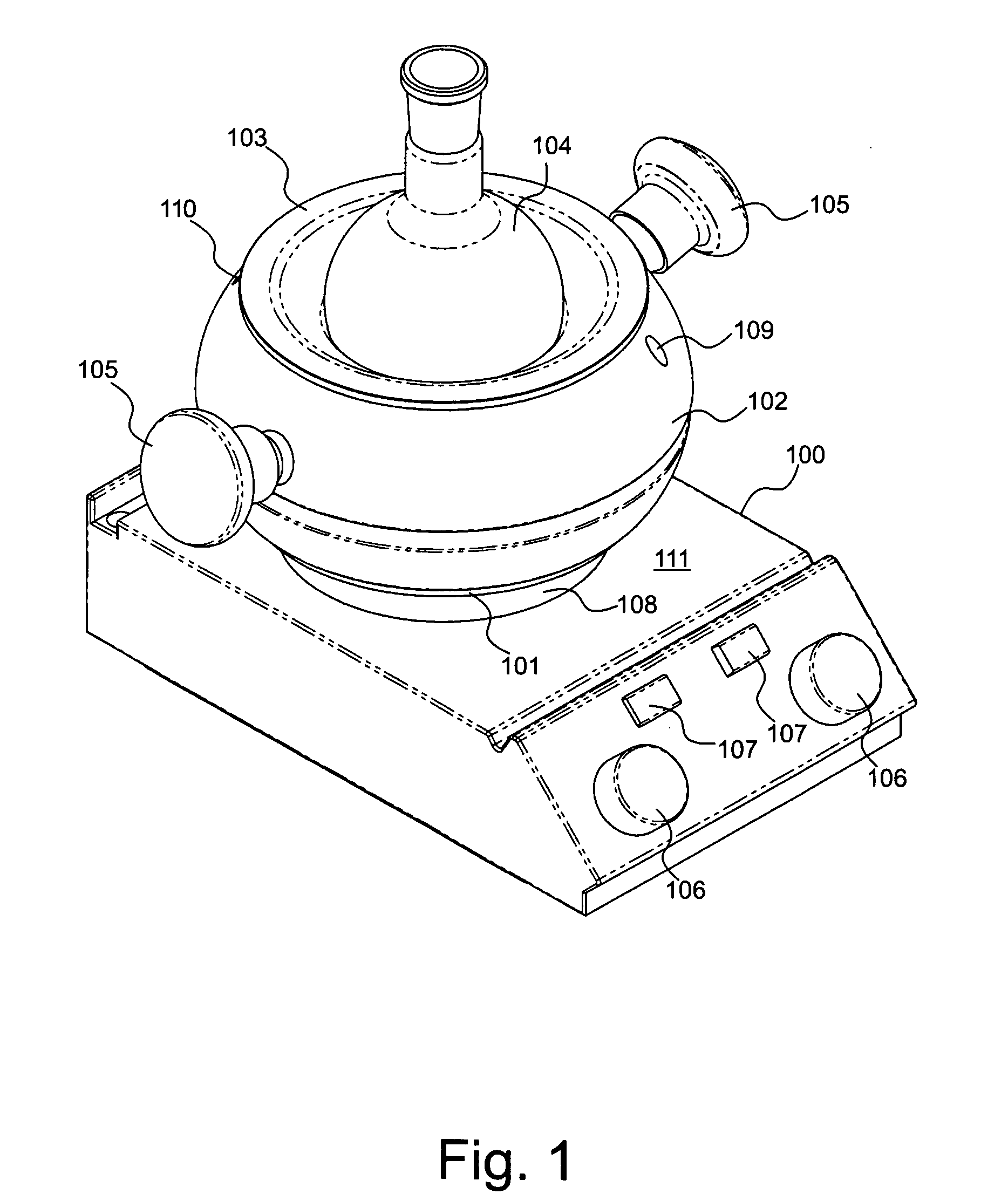
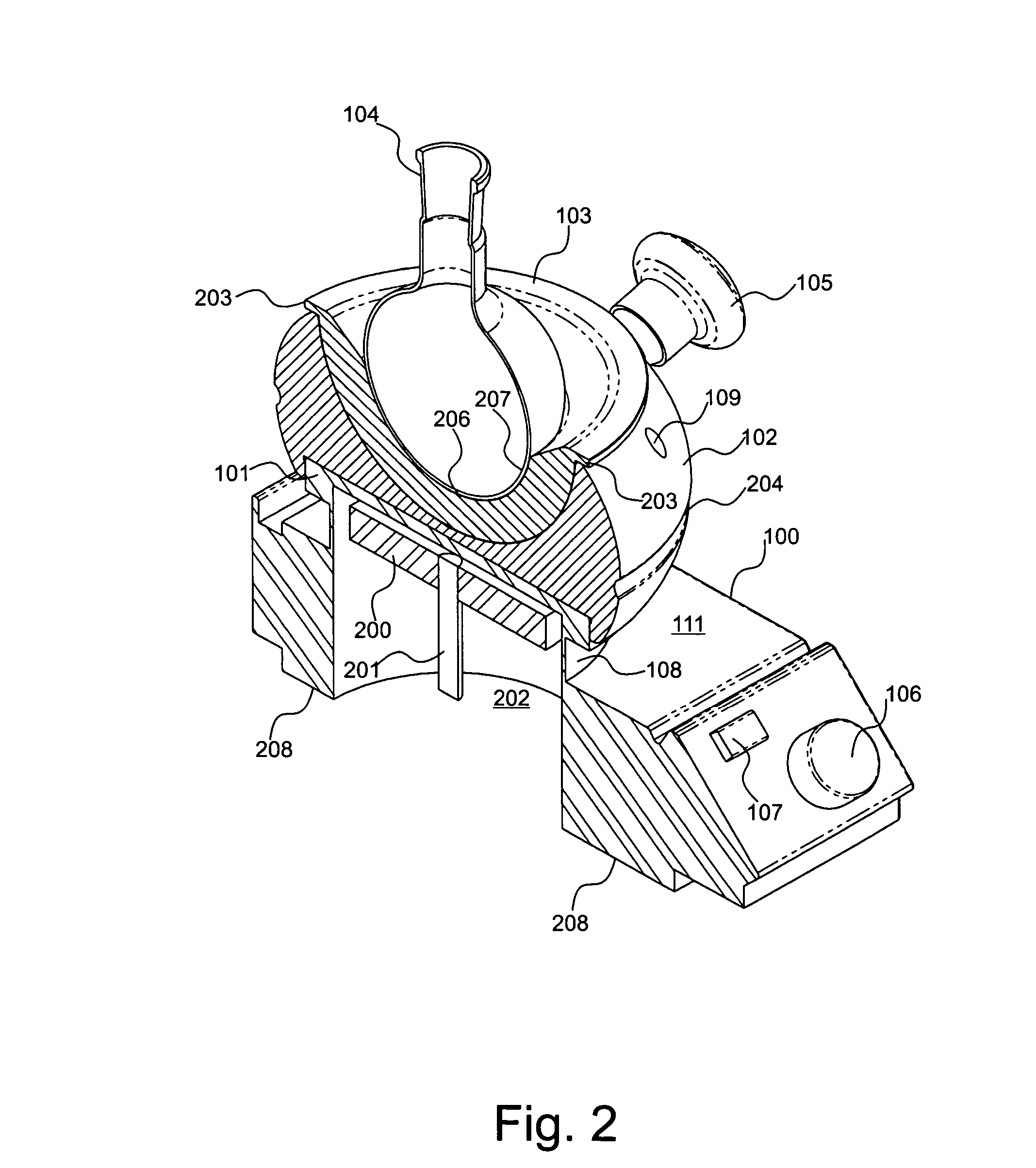
[0046] Within this specification, the term ‘reaction plate’ includes a magnetic stirrer plate; a hotplate and; a magnetic stirrer hotplate typically found within the art and used within a laboratory environment to provide heat or a stirring effect to a reaction medium housed within a reaction vessel.

[0047] Within this specification, reference to the central positioning of the flask, insert or recessed portion of the base unit relative to the reaction plate includes an alignment of a central...


PUM


Abstract

A reaction vessel support device for mounting on a magnetic stirrer hotplate. The modular device comprises a base unit capable of positioning and seating at the reaction hotplate, and an insert formed non-integrally with the base unit comprising a reaction vessel receiving portion capable of seating and locating about a portion of a reaction vessel. At any one time, the base unit is capable of accommodating a plurality of different shaped and sized inserts each insert being configured to seat and support a specific reaction vessel of particular shape and size. The device therefore serves as a magnetic stirrer hotplate adapter.

Description

BACKGROUND OF THE INVENTION [0001] (1) Field of the Invention [0002] The present invention relates to a device for positioning at a reaction plate, the device being configured to seat a reaction vessel at the reaction plate. [0003] (2) Description of the Related Art [0004] Laboratory based chemical reactions are typically carried out in a reaction vessel and where the reaction medium is liquid based, the reaction vessel is typically a round bottomed glass flask, commonly borosilicate, which is sold under the brand name Pyrex® by Corning of Corning, N.Y. [0005] In order to drive the reaction heat is supplied to the reaction vessel which in turn transfers the heat to the reaction medium. The common bunsen burner represents one of the more primitive sources of heat used in the laboratory to heat reaction vessels. A further example is the commonly used oil bath in which the oil is heated by heating elements located within the bath. Oil baths have found particular use where elevated temp...

Claims


Application Information

Patent Timeline
Patent Type & Authority Applications(United States)
IPC IPC(8): B01L9/00
CPCB01F13/0818B01L3/08B01L7/00B01L9/00B01L2200/025B01L2300/1805Y10S248/901B01F33/452
Inventor FORDHAM, MARTYN
Owner ASYNT
Why Eureka
Try Eureka