Cuff for blood pressure monitor, and blood pressure monitor having the same

a technology for blood pressure monitors and monitors, which is applied in the field of blood pressure monitors and blood pressure monitors, can solve the problems of deteriorating measurement accuracy, short length in the axial direction of the measurement site covered by the cuff, and difficulty in sufficiently pressing the artery for avascularization, so as to prevent lateral displacement of the cuff, high blood pressure, and high performance.

Inactive Publication Date: 2010-09-14
OMRON HEALTHCARE CO LTD
View PDF16 Cites 16 Cited by
  • Summary
  • Abstract
  • Description
  • Claims
  • Application Information

AI Technical Summary

Benefits of technology

[0016]An object of the present invention is to provide a cuff for a blood pressure monitor capable of preventing lateral displacement of the cuff, and to thereby implement a highly reliable blood pressure monitor of high performance.
[0017]A cuff for a blood pressure monitor according to a first aspect of the present invention has a fluid bag inflated and deflated as a fluid comes in and out. The fluid bag includes an inner wall portion located on an inner side in the state where the cuff for a blood pressure monitor is wound around a living body, an outer wall portion located on an outer side than the inner wall portion, and a side wall portion connecting a side end portion of the inner wall portion and a side end portion of the outer wall portion and folded inwards in a width direction of the fluid bag in a deflated state where the fluid bag is not pressurized to thereby form a gusset at a side end portion of the fluid bag. A joined portion for reducing expansion of the gusset formed by the side wall portion is provided at a region of the side end portion of the fluid bag in its winding direction around the living body.
[0018]As such, by forming the joined portion for reducing expansion of the gusset formed by the side wall portion in a region of the fluid bag in its winding direction around the living body, a change in shape of the side end portion of the fluid bag is restricted by the presence of the joined portion, and accordingly, it is possible to prevent lateral displacement of the fluid bag and uniform distribution of the pressing force over the measurement site is realized. Accordingly, it is possible to provide a highly reliable cuff for a blood pressure monitor, and the blood pressure value can be measured with high precision. It is noted that “reducing expansion of the gusset” herein not only refers to making the expansion of the gusset smaller than in the other region, but also refers to completely eliminating the gusset in the relevant region.

Problems solved by technology

However, if the width of the cuff is narrowed, the length in the axial direction of the measurement site covered by the cuff becomes short, in which case it would be difficult to sufficiently press the artery for avascularization.
When such protruding portion 190 is generated, it is not possible to efficiently and uniformly press air bag 150 against wrist 300, in which case sufficient avascularization performance cannot be obtained, resulting in deterioration of measurement accuracy.
It poses a serious problem especially in the configuration where gussets are formed at both side end portions of air bag 150 for the purposes of preventing degradation of measurement accuracy attributable to reduction in width of cuff 130.

Method used


Image

  • Cuff for blood pressure monitor, and blood pressure monitor having the same
  • Cuff for blood pressure monitor, and blood pressure monitor having the same
  • Cuff for blood pressure monitor, and blood pressure monitor having the same

Examples


example 1

[0103]FIG. 5A is a schematic perspective view of an air bag contained in a cuff for a blood pressure monitor according to Example 1 based on the present embodiment, with a part of the air bag being cut out. FIG. 5B is a schematic cross sectional view taken along the line VB-VB in FIG. 5A, and FIG. 5C is a schematic cross sectional view taken along the line VC-VC in FIG. 5A. FIG. 6 is an enlarged view of a region VI shown in FIG. 5C.

[0104]As shown in FIGS. 5A-5C, the air bag 150A of the cuff for a blood pressure monitor of the present example is formed into a bag shape using two resin sheets 151, 152. More specifically, resin sheet 151 of an approximately rectangular shape in two dimensions and resin sheet 152 of an approximately rectangular shape in two dimensions and slightly wider than resin sheet 151 are laid one on the other and their rims are melted and bonded to form air bag 150A having an inflated / deflated space 166 therein.

[0105]Resin sheet 152 constitutes an inner wall port...

example 2

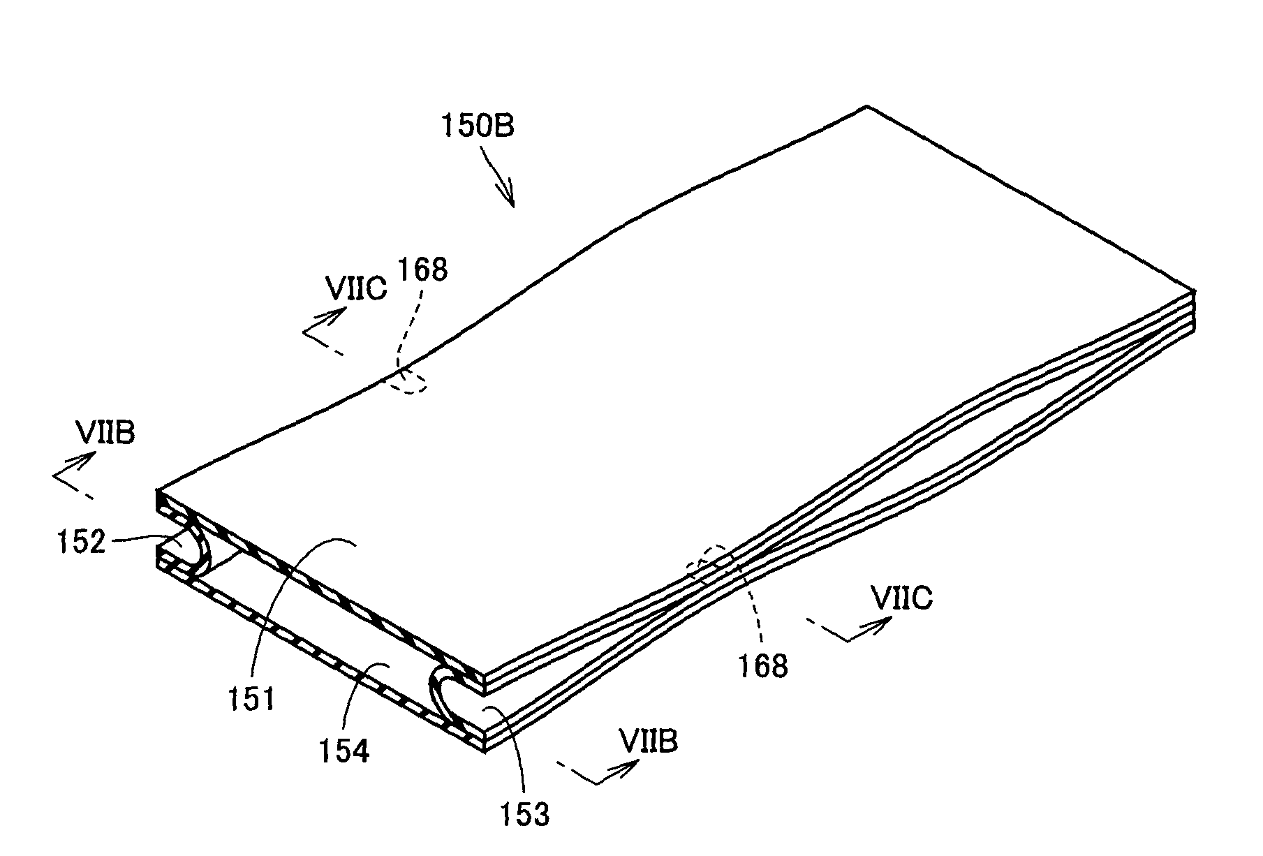
[0114]FIG. 7A is a schematic perspective view of an air bag contained in a cuff for a blood pressure monitor according to Example 2 based on the present embodiment, with a part of the air bag being cut out. FIG. 7B is a schematic cross sectional view taken along the line VIIB-VIIB in FIG. 7A, and FIG. 7C is a schematic cross sectional view taken along the line VIIC-VIIC in FIG. 7A. FIG. 8 is an enlarged view of a region VIII shown in FIG. 7C.

[0115]As shown in FIGS. 7A-7C, the air bag 150B of the cuff for a blood pressure monitor of the present example is formed into a bag shape using four resin sheets 151, 152, 153 and 154. More specifically, two resin sheets 151, 154 of an approximately rectangular shape in two dimensions are laid one on the other, and the side end portions of these two resin sheets 151, 154 are connected using resin sheets 152, 153 of an approximately rectangular shape in two dimensions and narrow in width, respectively, to form air bag 150B. Resin sheets 151, 152...

example 3

[0123]FIG. 9A is a schematic perspective view of an air bag contained in a cuff for a blood pressure monitor according to Example 3 based on the present embodiment, with a part of the air bag being cut out. FIG. 9B is a schematic cross sectional view taken along the line IXB-IXB in FIG. 9A, and FIG. 9C is a schematic cross sectional view taken along the line IXC-IXC in FIG. 9A. FIG. 10 is an enlarged view of a region X shown in FIG. 9C.

[0124]As shown in FIGS. 9A-9C, the air bag 150C of the cuff for a blood pressure monitor of the present example is formed into a bag shape using four resin sheets 151, 152, 153 and 154. More specifically, two resin sheets 151, 152 of an approximately rectangular shape in two dimensions are laid one on the other and their rims are melted and bonded to form a first bag member having a first inflated / deflated space 166a therein, two resin sheets 153, 154 of an approximately rectangular shape in two dimensions are laid one on the other and their rims are ...


PUM


Abstract

A cuff for a blood pressure monitor has an air bag inflated / deflated as the air comes in / out. The air bag has an inner wall portion located on the inner side in the fitted state of the cuff and an outer wall portion located outer than the inner wall portion, and a side wall portion connecting side end portions of the inner and outer wall portions and folded inwards in the deflated state of the air bag to form a gusset at each side end portion of the air bag. A bonded portion is provided at a region of the air bag in its winding direction around the living body, for reducing expansion of the gusset formed by the side wall portion. Thus, occurrence of lateral displacement of the cuff is prevented, and a highly reliable blood pressure monitor of high performance can be obtained.

Description

BACKGROUND OF THE INVENTION[0001]1. Field of the Invention[0002]The present invention relates to a cuff for a blood pressure monitor having a fluid bag for pressing a living body for avascularization of an artery, and a blood pressure monitor provided with the same.[0003]2. Description of the Background Art[0004]Generally, to measure a blood pressure value, a cuff provided with a fluid bag for pressing an artery located within a living body is wound around the body surface, and arterial pressure pulse waves caused in the artery by inflation / deflation of the fluid bag are detected to measure the blood pressure value. Here, the cuff refers to a band-shaped structure having a bladder, which can be wound around a part of a living body, for use in measurement of arterial pressure of an upper limb, a lower limb or the like by introducing fluid such as gas or liquid into the bladder. Thus, the cuff represents the concept including the fluid bag as well as members for winding the fluid bag ...

Claims


Application Information

Patent Timeline
Patent Type & Authority Patents(United States)
IPC IPC(8): A61B5/02
CPCA61B5/02233A61B17/135A61B5/022
Inventor KARO, HIROMICHISANO, YOSHIHIKOKISHIMOTO, HIROSHITSURUMI, YOSHINORI
Owner OMRON HEALTHCARE CO LTD
Why Eureka
Try Eureka