Elevator System Having a Flat Belt with Wedge-Shaped Ribs

a technology of wedge-shaped ribs and elevators, which is applied in the direction of elevators, mechanical equipment, transportation and packaging, etc., can solve the problems of not optimally adapting to the requirements of the support means of the elevator cage, formation of cracks, and heavy and expensiv

Active Publication Date: 2009-07-02
INVENTIO AG
View PDF15 Cites 15 Cited by
  • Summary
  • Abstract
  • Description
  • Claims
  • Application Information

AI Technical Summary

Benefits of technology

[0009]Pursuant to this task, one aspect of the present invention resides in an elevator installation having a support means of flat belt form which has at least on a running surface facing the drive pulley several ribs extending parallel in the belt longitudinal direction, wherein at least two tensile carriers oriented in the belt longitudinal direction are present per rib and the sum of the cross-sectional areas of all tensile carriers amounts to at least 25%, preferably 30% to 40%, of the total cross-sectional area of the support means. For ascertaining the total cross-sectional area of the tensile carriers, the cross-section defined by the outer diameter thereof is to be taken into account.
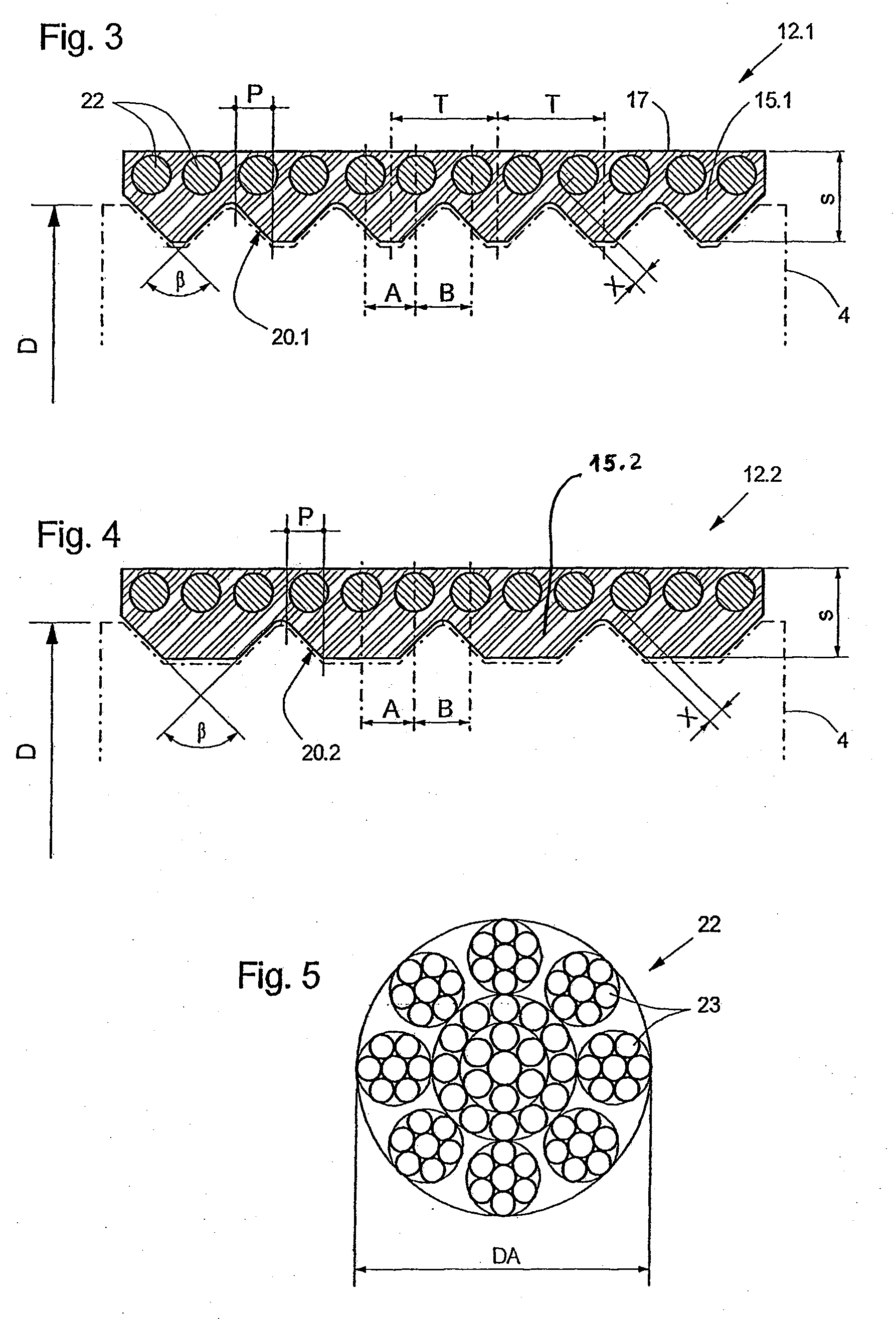
[0010]Through the distribution of the load to two tensile carriers (with the requisite cross-section) per rib it is achieved that the tensile means when the support means runs over belt pulleys with small diameters are exposed to smaller alternating bending stresses than if a single tensile carrier with correspondingly larger diameter were used per rib. With the indicated relationship between the sum of the cross-sectional areas of all tensile carriers and the cross-sectional area of the support means there is defined a support means which has optimally small dimensions and material quantities. The optimum small dimensions also have the consequence of correspondingly small alternating bending stresses in the material of the belt body. Materials (rubber, lastomer) can therefore be selected for production of the belt body which have a lower permissible bending stress, but tolerate higher area pressures between tensile carriers and belt body.
[0011]According to a preferred refinement of the invention there are used in the support means tensile carriers with a substantially round cross-section, the outer diameter of which amounts to at least 30%, preferably 35% to 40%, of the rib spacing. As rib spacing there is to be understood the spacing between adjacent ribs of a support means, which is usually the same between all ribs of a specific support means. In the case of a support means constructed in accordance with this rule it is ensured that the forces which are to be transmitted by the tensile carriers via the belt body to a drive pulley or a deflecting roller are optimally distributed in the belt body and the area pressures arising between tensile carriers and belt body are optimally small. The risk is thereby minimised that a loaded tensile carrier cuts through the belt body.
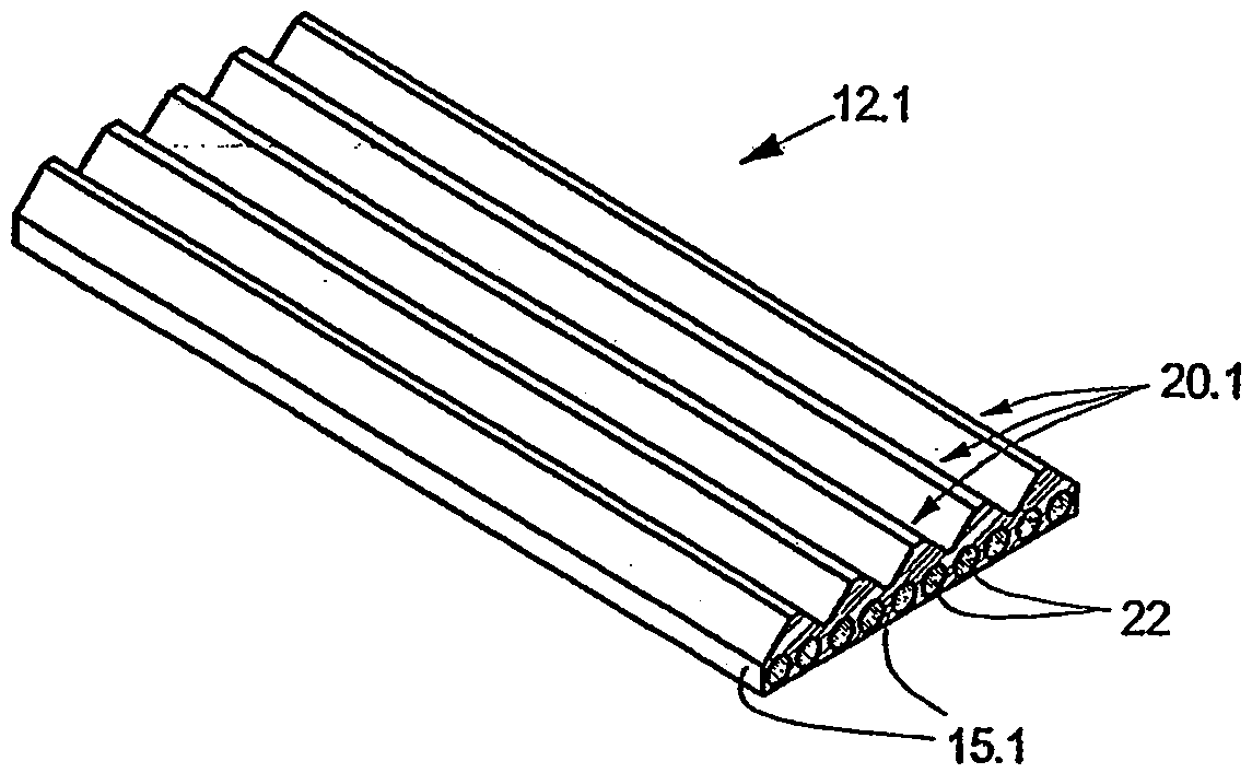
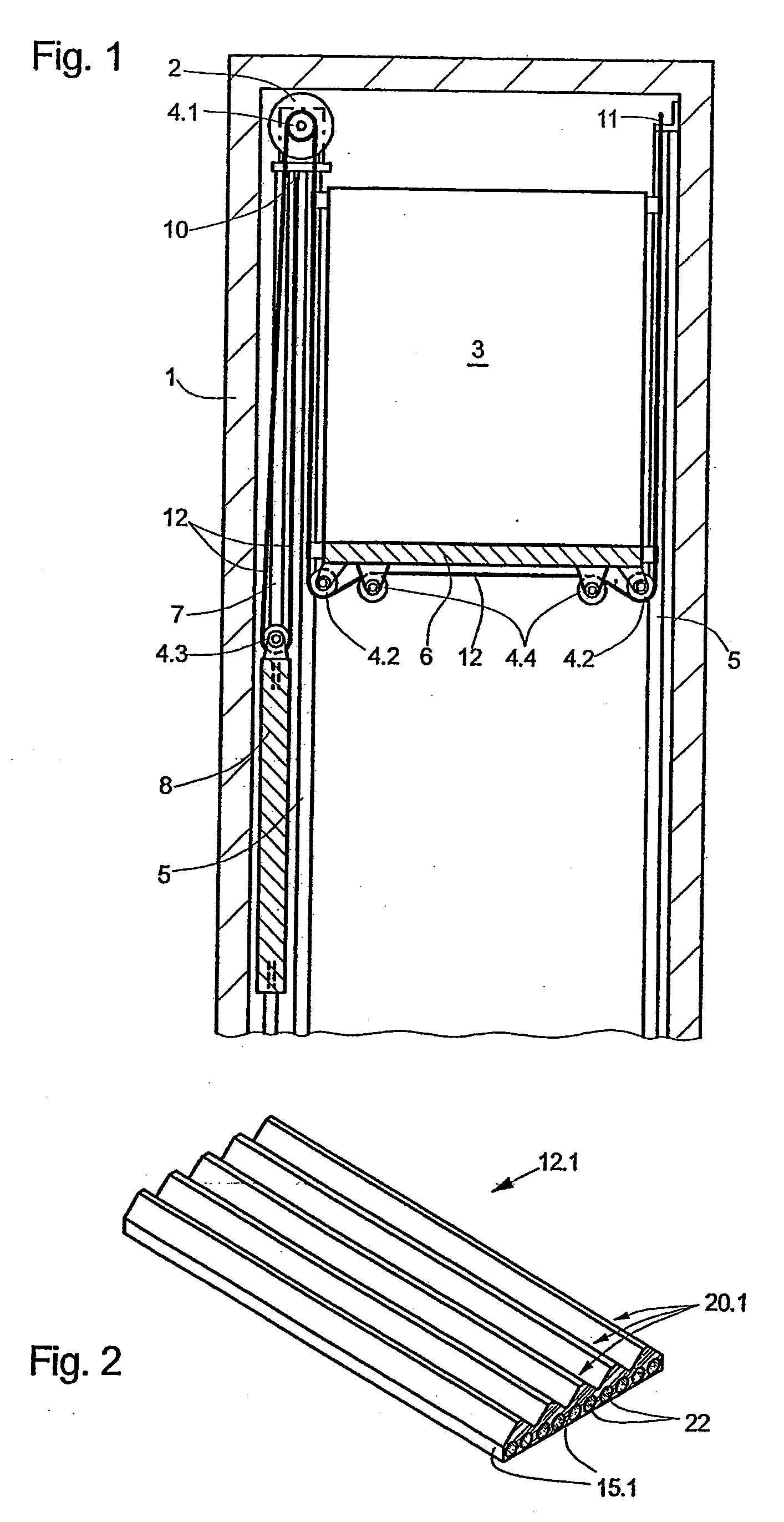
[0012]Advantageously the ribs have a wedge-shaped cross-section with a flank angle of 60° to 120°, wherein the range of 80° to 100° is to be preferred. The angle present between the two side surfaces (flank) of a wedge-shaped rib is termed flank angle. With flank angles of 60° to 120° it is ensured on the one hand that when the support means runs over belt pulleys no jamming between the ribs and the grooves, which are formed to be complementary thereto, of the belt pulleys arises. Running noises as also excitation of vibrations of the wedge-ribbed belt are thereby reduced. On the other hand, with such flank angles a sufficient guidance of the support means on the belt pulleys can be achieved, which prevents the lateral displacement of the support means relative to the belt pulleys.
[0014]Optimally small dimensions and low weight of the support means are achievable if the minimum spacing of the outer contour of a tensile carrier from a surface of a rib amounts to at most 20% of the total thickness of the support means. The total thickness of the belt body with the grooves is to be understood as total thickness.
[0015]According to a preferred refinement of the invention the tensile carriers associated with a rib are so arranged that a respective outer tensile carrier lies substantially in the region of the perpendicular projection of each flank of the wedge-shaped rib. A projection oriented perpendicularly to the plane of the flat side of the support means is termed perpendicular projection and by “substantially” there is to be understood that at least 90% of the cross-sectional area of the respective tensile carrier lies within the said projection.
[0015]According to a preferred refinement of the invention the tensile carriers associated with a rib are so arranged that a respective outer tensile carrier lies substantially in the region of the perpendicular projection of each flank of the wedge-shaped rib. A projection oriented perpendicularly to the plane of the flat side of the support means is termed perpendicular projection and by “substantially” there is to be understood that at least 90% of the cross-sectional area of the respective tensile carrier lies within the said projection.
[0017]With the two arrangements, defined in the foregoing, of the tensile carriers in the flank region it is guaranteed that when running around a belt pulley no tensile carrier has to be supported by that point of the belt body which has the deepest notching formed by the grooves lying between the ribs.
[0018]In order to obtain support means which for a given tensile loading have a smallest possible longitudinal stretching, tensile carriers of steel wire cables are used. Steel wire cables are less stretched, for the same loading, than, for example, tensile carriers with the same cross-section of conventional synthetic fibres.

Problems solved by technology

The wedge-ribbed belts known from WO 03 / 043926 have certain disadvantages, i.e. they are not optimally adapted to the requirements of a support means for eleavtor cages.
In the case of the cross-section, which is given by the required load-bearing strength, of the tensile carriers this means that the disclosed wedge ribbed belts on the one hand have more than the absolutely necessary amount of material for the belt body and thus are too heavy and too expensive.
On the other hand, the material of the belt body, which is relatively high in bending direction, is needlessly strongly loaded by alternating bending stresses when the support means runs around a drive pulley or a deflecting roller of small diameter, which can lead to formation of cracks and premature failure of the support means.

Method used


Image

  • Elevator System Having a Flat Belt with Wedge-Shaped Ribs
  • Elevator System Having a Flat Belt with Wedge-Shaped Ribs
  • Elevator System Having a Flat Belt with Wedge-Shaped Ribs

Examples


Embodiment Construction

[0026]FIG. 1 shows a section through an elevator system according to the invention installed in an elevator shaft 1. Essentially illustrated are:

[0027]a drive unit 2, which is fixed in the elevator shaft 1, with a drive pulley 4.1;

[0028]an elevator cage 3, which is guided at cage guide rails 5, with cage support rollers 4.2 mounted below the cage floor 6;

[0029]a counterweight 8, which is guided at counterweight guide rails 7, with a counterweight support roller 4.3; and

[0030]a support means, which is constructed as a wedge ribbed belt 12, for the elevator cage 3 and the counterweight 8, which support means transmits the drive force from the drive pulley 4.1 of the drive unit 2 to the elevator cage and the counterweight. (In the case of an actual elevator installation, at least two wedge ribbed belts arranged in parallel are present).

[0031]The wedge ribbed belt 12 serving as support means is fastened at its end below the drive pulley 4.1 to a first support means fixing point 10. From...


PUM

PropertyMeasurementUnit
flank angleaaaaaaaaaa
flank anglesaaaaaaaaaa

Abstract

An elevator installation is provided that includes an elevator cage, a drive pulley, at least one support means formed as a flat belt, and a drive engine which drives the at least one support means, which carries the elevator cage, by way of the drive pulley. In the elevator installation, the support means has, at least on a running surface facing the drive pulley, several ribs of wedge-shaped or trapezium-shaped cross-section which extend parallel in a longitudinal direction of the support means and further has several tensile carriers oriented in the longitudinal direction of the support means. The tensile carriers are sized so that a total cross-sectional area of all the tensile carriers amounts to 30%-40% of a cross-sectional area of the support means. The tensile carriers may be distributed in a transverse direction of the support means so that exactly two tensile carriers are associated with each of the ribs, the tensile carriers having an outer diameter equal to 35%-40% of a rib spacing (T).

Description

CROSS-REFERENCE TO RELATED APPLICATIONS[0001]The present application is a continuation of the co-pending patent application Ser. No. 10 / 585,563, filed Aug. 1, 2006, the entire contents of which are incorporated herein by reference, which claims priority to PCT / EP2004 / 014723, filed on Dec. 27, 2004, which claims priority to European Patent Application No. 04405008.6, filed on Jan. 6, 2004.BACKGROUND OF THE INVENTION[0002]The subject of the invention is an elevator installation.[0003]Elevator installations of the kind according to the invention usually comprise an elevator cage and a counterweight, which are movable in an elevator shaft or along free-standing guide devices. For producing the movement the elevator installation comprises at least one drive with at least one respective drive pulley, which, by way of support means and / or drive means, support the elevator cage and the counterweight and transmit the required drive forces to these.[0004]In the following, for the sake of simp...

Claims


Application Information

Patent Timeline
Patent Type & Authority Applications(United States)
IPC IPC(8): B66B11/08B66B7/06B66B11/00D07B1/16D07B1/22
CPCB66B7/062D07B2501/2007D07B2201/2087D07B1/22
Inventor ACH, ERNST
Owner INVENTIO AG
Why Eureka
Try Eureka