Elevator system having a flat belt with wedge-shaped ribs

a wedge-shaped belt and elevator technology, applied in elevators, hoisting equipment, transportation and packaging, etc., can solve the problems of not optimally adapting to the requirements of elevator cage support means, too heavy and expensive, formation of cracks, etc., to reduce the noise of running noise as well as excitation of vibration of the wedge-ribbed belt, and the effect of reducing the bending stress

Active Publication Date: 2010-07-20
INVENTIO AG
View PDF21 Cites 17 Cited by
  • Summary
  • Abstract
  • Description
  • Claims
  • Application Information

AI Technical Summary

Benefits of technology

[0009]The present invention is based on the task of creating an elevator installation of the afore-described kind in which the stated disadvantages are not present, i.e. that the an elevator installation comprises a support means of flat belt form with ribs, which in the case of use with minimum belt pulley diameters and for a predetermined load-bearing capability has minimum dimensions and minimum weight, wherein the tensile carriers and the belt body are exposed to the smallest possible loads so that an optimum service life is guaranteed.
[0011]Through the distribution of the load to two tensile carriers (with the requisite cross-section) per rib it is achieved that the tensile means when the support means runs over belt pulleys with small diameters are exposed to smaller alternating bending stresses than if a single tensile carrier with correspondingly larger diameter were used per rib. With the indicated relationship between the sum of the cross-sectional areas of all tensile carriers and the cross-sectional area of the support means there is defined a support means which has optimally small dimensions and material quantities. The optimum small dimensions also have the consequence of correspondingly small alternating bending stresses in the material of the belt body. Materials (rubber, elastomer) can therefore be selected for production of the belt body which have a lower permissible bending stress, but tolerate higher area pressures between tensile carriers and belt body.
[0012]According to a preferred refinement of the invention there are used in the support means tensile carriers with a substantially round cross-section, the outer diameter of which amounts to at least 30%, preferably 35% to 40%, of the rib spacing. As rib spacing there is to be understood the spacing between adjacent ribs of a support means, which is usually the same between all ribs of a specific support means. In the case of a support means constructed in accordance with this rule it is ensured that the forces which are to be transmitted by the tensile carriers via the belt body to a drive pulley or a deflecting roller are optimally distributed in the belt body and the area pressures arising between tensile carriers and belt body are optimally small. The risk is thereby minimised that a loaded tensile carrier cuts through the belt body.
[0013]Advantageously the ribs have a wedge-shaped cross-section with a flank angle of 60° to 120°, wherein the range of 80° to 100° is to be preferred. The angle present between the two side surfaces (flank) of a wedge-shaped rib is termed flank angle. With flank angles of 60° to 120° it is ensured on the one hand that when the support means runs over belt pulleys no jamming between the ribs and the grooves, which are formed to be complementary thereto, of the belt pulleys arises. Running noises as also excitation of vibrations of the wedge-ribbed belt are thereby reduced. On the other hand, with such flank angles a sufficient guidance of the support means on the belt pulleys can be achieved, which prevents the lateral displacement of the support means relative to the belt pulleys.
[0015]Optimally small dimensions and low weight of the support means are achievable if the minimum spacing of the outer contour of a tensile carrier from a surface of a rib amounts to at most 20% of the total thickness of the support means. The total thickness of the belt body with the grooves is to be understood as total thickness.

Problems solved by technology

The wedge-ribbed belts known from WO 03 / 043926 have certain disadvantages, i.e. they are not optimally adapted to the requirements of a support means for elevator cages.
In the case of the cross-section, which is given by the required load-bearing strength, of the tensile carriers this means that the disclosed wedge ribbed belts on the one hand have more than the absolutely necessary amount of material for the belt body and thus are too heavy and too expensive.
On the other hand, the material of the belt body, which is relatively high in bending direction, is needlessly strongly loaded by alternating bending stresses when the support means runs around a drive pulley or a deflecting roller of small diameter, which can lead to formation of cracks and premature failure of the support means.

Method used


Image

  • Elevator system having a flat belt with wedge-shaped ribs
  • Elevator system having a flat belt with wedge-shaped ribs
  • Elevator system having a flat belt with wedge-shaped ribs

Examples


Embodiment Construction

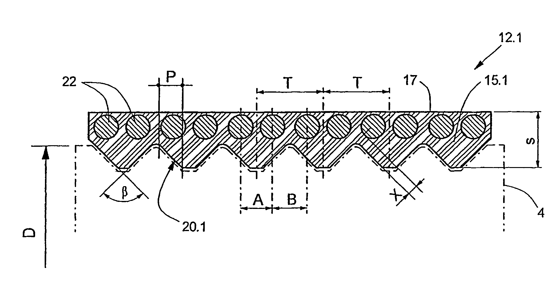
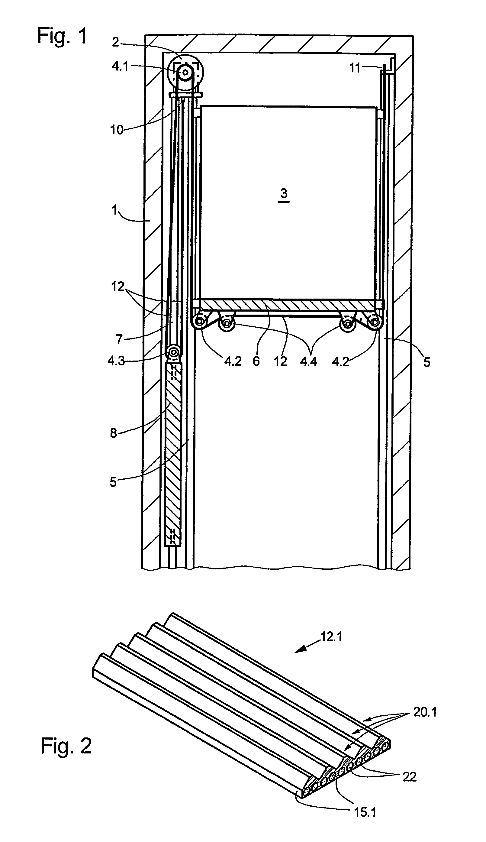
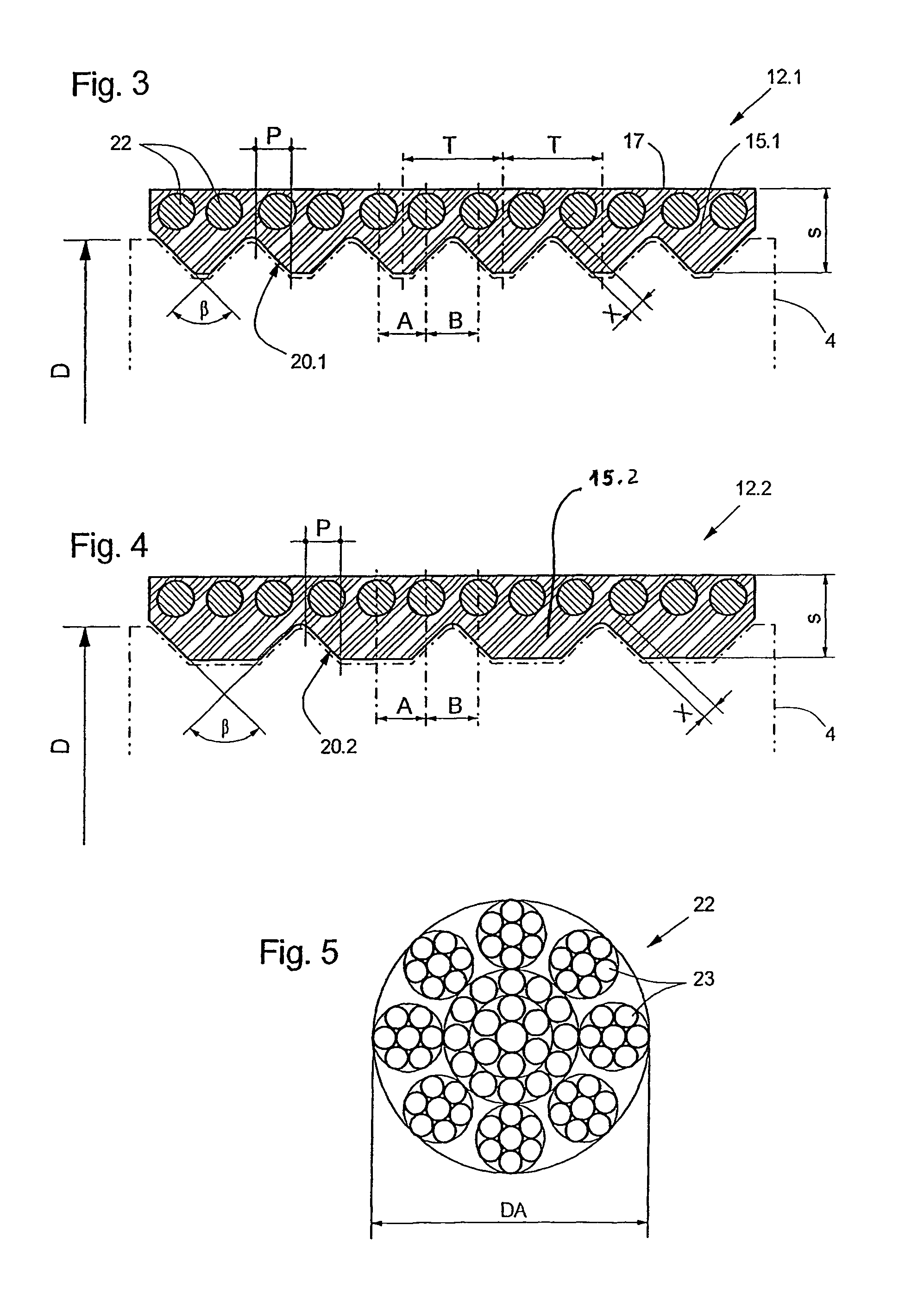
[0027]FIG. 1 shows a section through an elevator system according to the invention installed in an elevator shaft 1. Essentially illustrated are:[0028]a drive unit 2, which is fixed in the elevator shaft 1, with a drive pulley 4.1[0029]an elevator cage 3, which is guided at cage guide rails 5, with cage support rollers 4.2 mounted below the cage floor 6[0030]a counterweight 8, which is guided at counterweight guide rails 7, with a counterweight support roller 4.3[0031]a support means, which is constructed as a wedge ribbed belt 12, for the elevator cage 3 and the counterweight 8, which support means transmits the drive force from the drive pulley 4.1 of the drive unit 2 to the elevator cage and the counterweight. (In the case of an actual elevator installation, at least two wedge ribbed belts arranged in parallel are present)

[0032]The wedge ribbed belt 12 serving as support means is fastened at its end below the drive pulley 4.1 to a first support means fixing point 10. From this it...


PUM

PropertyMeasurementUnit
flank angleaaaaaaaaaa
flank anglesaaaaaaaaaa

Abstract

The invention relates to a lift system wherein a drive unit (2) drives, by means of a driving disk (4.1), a flat belt-type carrier means (12.1, 12.2) which carries the lift cage (3). Said flat belt-type carrier means comprises several ribs (20.1, 20.2) which extend in a parallel manner in a longitudinal direction of the carrier means on a bearing surface which is orientated towards the driving disk (4.1) and each rib comprises at least two traction carriers (22) which are orientated in a longitudinal direction of the carrier means. The whole cross-sectional surface of all the traction carriers (22) is at least 25% of the cross-section surface of the carrier means.

Description

PRIORITY CLAIM[0001]This is a U.S. national stage of application No. PCT / EP2204 / 014723, filed on Dec. 27, 2004. Priority is claimed on that application and on the following application:[0002]Country: Europe, Application No.: 04405008.6, Filed: Jan. 6, 2004.BACKGROUND OF THE INVENTION[0003]Subject of the invention is an elevator installation.[0004]Elevator installations of the kind according to the invention usually comprise an elevator cage and a counterweight, which are movable in an elevator shaft or along free-standing guide devices. For producing the movement the elevator installation comprises at least one drive with at least one respective drive pulley, which, by way of support means and / or drive means, support the elevator cage and the counterweight and transmit the required drive forces to these.[0005]In the following, for the sake of simplicity the support means and / or drive means are termed only support means.[0006]An elevator system without an engine room is known from WO...

Claims


Application Information

Patent Timeline
Patent Type & Authority Patents(United States)
IPC IPC(8): B66B11/04F16G1/00F16G1/28F16G9/00B66D1/00B66B11/08B66B7/06B66B11/00D07B1/16D07B1/22
CPCB66B7/062D07B1/22D07B2201/2087D07B2501/2007
Inventor ACH, ERNST
Owner INVENTIO AG
Why Eureka
Try Eureka