
A parking channel gate control system

A control system, access gate technology, applied in electrical program control, program control in sequence/logic controllers, roads, etc., can solve problems such as failure, entanglement of responsibilities, reduce the probability of accidents, etc., to achieve design Reasonable, stable performance, easy to use effect

Inactive Publication Date: 2020-10-16
SHANGLUO UNIV
View PDF5 Cites 3 Cited by
  • Summary
  • Abstract
  • Description
  • Claims
  • Application Information

AI Technical Summary

Problems solved by technology

[0002] With the development of society and economy, people's living standards continue to improve, and cars have become the most common means of transportation for people. There are parking access gates on many occasions. The parking access gates can keep the entry and exit of cars in good order and reduce accidents. The probability of occurrence, and can record the information of vehicles entering and exiting. When the vehicle is released, the railing rises, and the vehicle falls through the rear railing. Due to technical or management reasons, the situation of the barriers smashing cars or people happens from time to time. There is a problem of entanglement in responsibility, which makes people pay more and more attention to the safety of access gates. However, now, the anti-smashing technologies used in parking access gates on the market are generally ground-sensing anti-smashing technology, infrared anti-smashing technology, Pressure wave anti-smashing technology and digital anti-smashing technology. The key to ground-sensing anti-smashing technology lies in the stability of the ground-sensing coil. If the ground feels interference, it may fail. The range of infrared radiation is small, and it is easily affected by rain and snow. Due to the interference of weather, the cost of digital anti-smashing technology is relatively high. Therefore, the present invention provides a parking access gate control system

Method used


Image

  • A parking channel gate control system
  • A parking channel gate control system
  • A parking channel gate control system

Examples


Embodiment Construction

[0017] In order to make the technical means, creative features, goals and effects achieved by the present invention easy to understand, the present invention will be further described below in conjunction with specific embodiments.

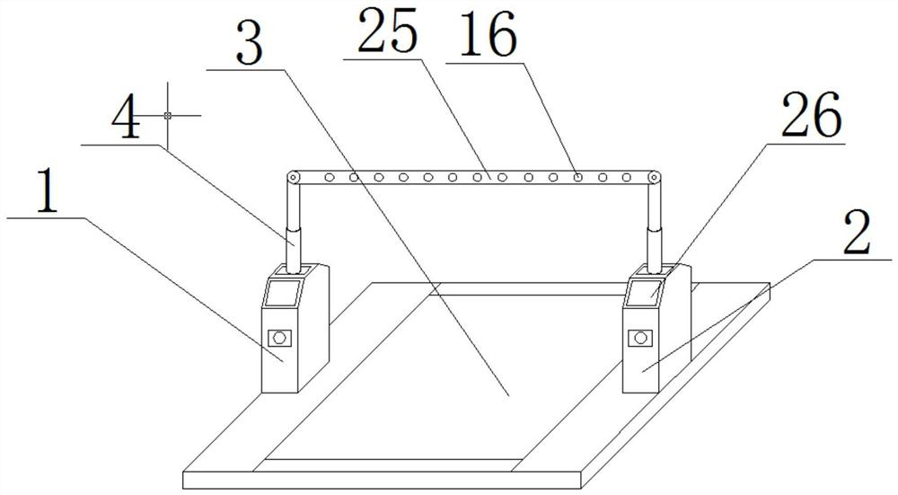
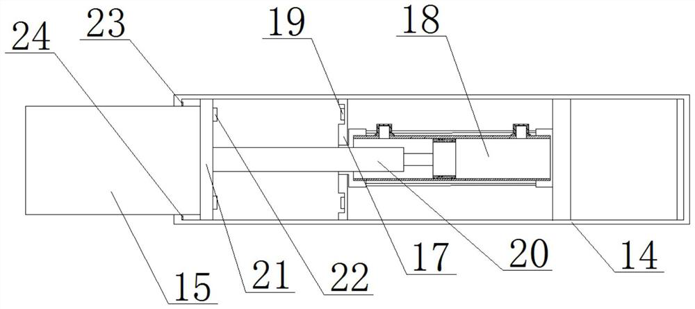
[0018] see Figure 1 to Figure 3 , the present invention provides a technical solution: a parking channel gate control system, including a channel gate body, the channel gate body includes a controller 26, a gate body 1, a gate body 2 and a support plate 3, the controller 26 includes a control unit and an intelligent processor. Lifting devices 4 are provided on the tops of the first gate body 1 and the second gate body 2. Cross bars 25 are arranged between the lift devices 4, and cross bars 25 are provided with LED lamp 16, the top of the support plate 3 is provided with a mounting groove 5, the mounting groove 5 is provided with a pressing plate 6, one side of the mounting groove 5 is provided with a track groove 7, and one side of the pressing p...


PUM


Abstract

The present invention provides a parking passage gate control system including a passage gate body. The passage gate body includes a gate body 1, a gate body 2 and a support plate. The tops of the gate body 1 and the gate body 2 are both provided with lifting devices. A crossbar is disposed between the lifting devices and is provided with an LED lamp. The top of the support plate is provided witha mounting slot. A pressing plate is disposed in the mounting slot. A side of the mounting slot is provided with a track groove. A stopping block is disposed on a side of the pressing plate. A hydraulic rod fallback switch is disposed on the inner side wall of the top of the track groove. A switch protection slot 1 and a groove are disposed on the inner side wall of the bottom of the mounting groove. The switch protection slot 1 is provided therein with a hydraulic rod raising switch and a spring 1. One end of the spring 1 sleeves the hydraulic rod raising switch. The parking passage gate withan anti-smashing function is reasonable in design, stable in anti-smashing performance and easy to use.

Description

technical field [0001] The invention relates to the technical field of passage management equipment, in particular to a parking passage gate control system. Background technique [0002] With the development of society and economy, people's living standards continue to improve, and cars have become the most common means of transportation for people. There are parking access gates on many occasions. The parking access gates can keep the entry and exit of cars in good order and reduce accidents. The probability of occurrence, and can record the information of vehicles entering and exiting. When the vehicle is released, the railing rises, and the vehicle falls through the rear railing. Due to technical or management reasons, the situation of the barriers smashing cars or people happens from time to time. There is a problem of entanglement in responsibility, which makes people pay more and more attention to the safety of access gates. However, now, the anti-smashing technologies...

Claims


Application Information

Patent Timeline
Patent Type & Authority Patents(China)
IPC IPC(8): E01F13/04G05B19/04
CPCE01F13/04E01F13/048G05B19/04
Inventor 辛建军
Owner SHANGLUO UNIV
Learn More