Method for manufacturing micro-perforated plate

A technology of micro-perforated plate and round hole, which is applied in building components, sound insulation, building structure, etc., can solve the problems of low production efficiency, difficult realization, and cost increase, and achieves low price, suitable for processing, and convenient installation. Effect

Pending Publication Date: 2019-04-02
BEIJING MUNICIPAL INST OF LABOUR PROTECTION
View PDF6 Cites 2 Cited by
  • Summary
  • Abstract
  • Description
  • Claims
  • Application Information

AI Technical Summary

Problems solved by technology

However, it has two disadvantages: First, this method can only produce micropores with larger apertures, generally above 0.5mm
According to Ma Dayou's theory, the micro-perforated plate can obtain better sound absorption performance when the aperture of the micro-hole is small. For the smaller aperture on the metal plate, such as below 0.3mm, mechanical methods are difficult to achieve. Even if it can be achieved, its production efficiency is not high, and the cost will increase significantly
Of course, this is mainly for metal sheets. For example, when processing micropores with ultra-fine diameters on thin films, fine needles can be used to open ultra-fine micropores below 0.1 mm, but the scope of use of this thin film material subject to great limitations
The second is the mold used by the mechanical method, the hole diameter and hole spacing are basically fixed, and it is difficult to adjust
However, to obtain a pore size below 0.1mm, this method has certain limitations and is difficult to achieve

Method used


Image

  • Method for manufacturing micro-perforated plate
  • Method for manufacturing micro-perforated plate

Examples


Embodiment 1

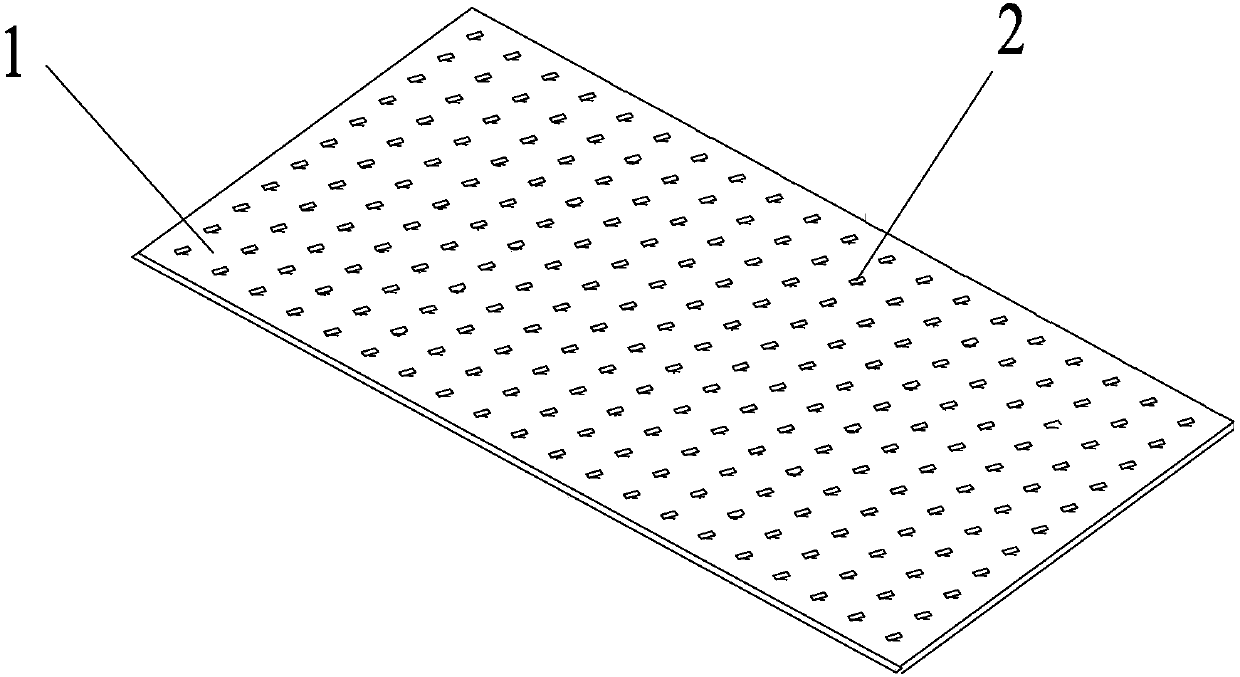
[0039] A method for manufacturing a micro-perforated plate, utilizing the heat-shrinkable property of the heat-shrinkable plate 1, processing millimeter-level holes on the heat-shrinkable plate, and making holes of the silk-meter level or below through heat-shrinkage.

[0040] In this embodiment, the heat-shrinkable plate is a PVC plate with a shrinkage ratio of 60%, and a circular hole 2 with a diameter of 2 mm is machined on a PVC plate with a thickness of 0.1 mm (see figure 1 ). The processed millimeter-scale holes are evenly distributed.

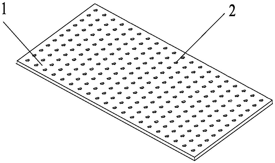
[0041] Millimeter-scale holes were processed on the heat-shrinkable plate at a temperature of 25° C., and the heat-shrinkable plate was heated in an oven at 160° C. until it shrank naturally, taken out and cooled, and a transparent PVC plate with a thickness of 3 mm was obtained. There are 0.2mm diameter holes on the board ( figure 2 ).

Embodiment 2

[0043] The processing method of this embodiment is the same as that of Embodiment 1, and the heat-shrinkable board is an opaque PVC board with a thickness of 2mm.

[0044] Triangular holes with a side length of 2 mm and elliptical holes with a major axis of 3 mm are processed by laser technology, and the holes are arranged to be non-uniformly distributed.

[0045]Then, heat the heat-shrinkable plate in an oven at 160° C., so that the heat-shrinkable plate naturally shrinks to obtain holes of silk rice level or below. The thickness of the plate becomes 20mm, and the size of the hole on the plate is 0.2mm-0.3mm.


PUM


Abstract

The invention provides a method for manufacturing a micro-perforated plate. Through the characteristic of heating shrinkage of a heat shrinkage plate, millimeter-level holes are machined in the heat shrinkage plate, and holes of the decimillimetre level or below are manufactured through heating shrinkage. Considering the defects that as for a traditional metal micro-perforated plate, a large number of holes of the millimeter level or below are difficult to manufacture in a thin plate, and the cost is high, through the characteristic of heating shrinkage of the heat shrinkage sheet, the millimeter-level holes are machined in the heat shrinkage plate and become micron-level holes through heating shrinkage. The micro-perforated plate structure is suitable for being machined, the price is low,mounting is convenient, exquisite patterns can be drawn, and the micro-perforated plate can be used for places, needing decoration and noise reduction, such as home decoration, halls, meeting rooms,hotels and sound barriers.

Description

technical field [0001] The invention belongs to the technical field of sound absorption, in particular to a method for making a micro-perforated plate Background technique [0002] According to the micro-perforated plate theory, it is required that the diameter of the micro-holes on the micro-perforated plate should be less than 1mm, that is, the micro-holes of the silk meter level. Therefore, in order to obtain a good sound absorption effect, the processing of the micro-holes is a very important issue. It has always been paid attention to by people studying the theory of micro-perforated plates. Generally speaking, the traditional mechanical processing method can meet the general needs of micro-holes above 0.5mm, but for smaller apertures, such as 0.1mm or higher precision requirements, other methods, such as laser and other modern methods, are required. Processing Technology. Since Ma Dayou proposed the sound-absorbing structure theory of micro-perforated plates in the 1...

Claims


Application Information

Patent Timeline
Patent Type & Authority Applications(China)
IPC IPC(8): E04B1/86
CPCE04B1/86E04B2001/848
Inventor 盖晓玲邢拓李贤徽张斌王芳蔡泽农
Owner BEIJING MUNICIPAL INST OF LABOUR PROTECTION
Why Eureka
Try Eureka