Industrial pipeline valve

A technology for industrial pipelines and valves, applied in the directions of lift valves, valve details, valve devices, etc., can solve problems such as inability to adjust flow, and achieve the effect of convenient fixing, saving time, and preventing shaking

Inactive Publication Date: 2019-04-02
康毛娣
View PDF8 Cites 5 Cited by
  • Summary
  • Abstract
  • Description
  • Claims
  • Application Information

AI Technical Summary

Problems solved by technology

[0004] The purpose of the present invention is to provide an industrial pipeline valve, which has the advantage of being able to adjust the flow rate, and solves the problem that the existing industrial pipeline valve cannot adjust the flow rate

Method used


Image

  • Industrial pipeline valve
  • Industrial pipeline valve
  • Industrial pipeline valve

Examples


Embodiment Construction

[0026] The following will clearly and completely describe the technical solutions in the embodiments of the present invention with reference to the accompanying drawings in the embodiments of the present invention. Obviously, the described embodiments are only some, not all, embodiments of the present invention. Based on the embodiments of the present invention, all other embodiments obtained by persons of ordinary skill in the art without making creative efforts belong to the protection scope of the present invention.

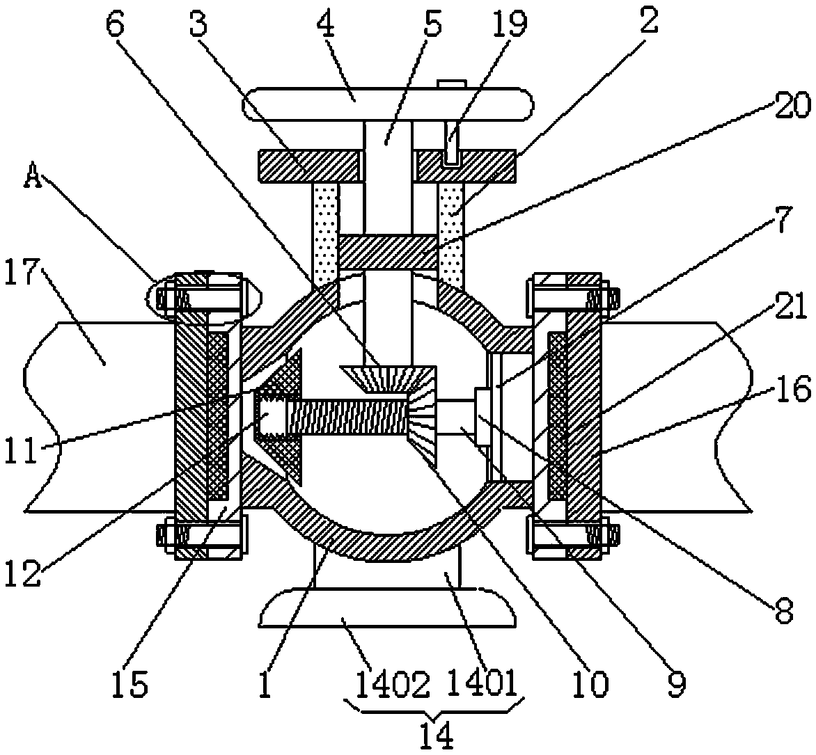
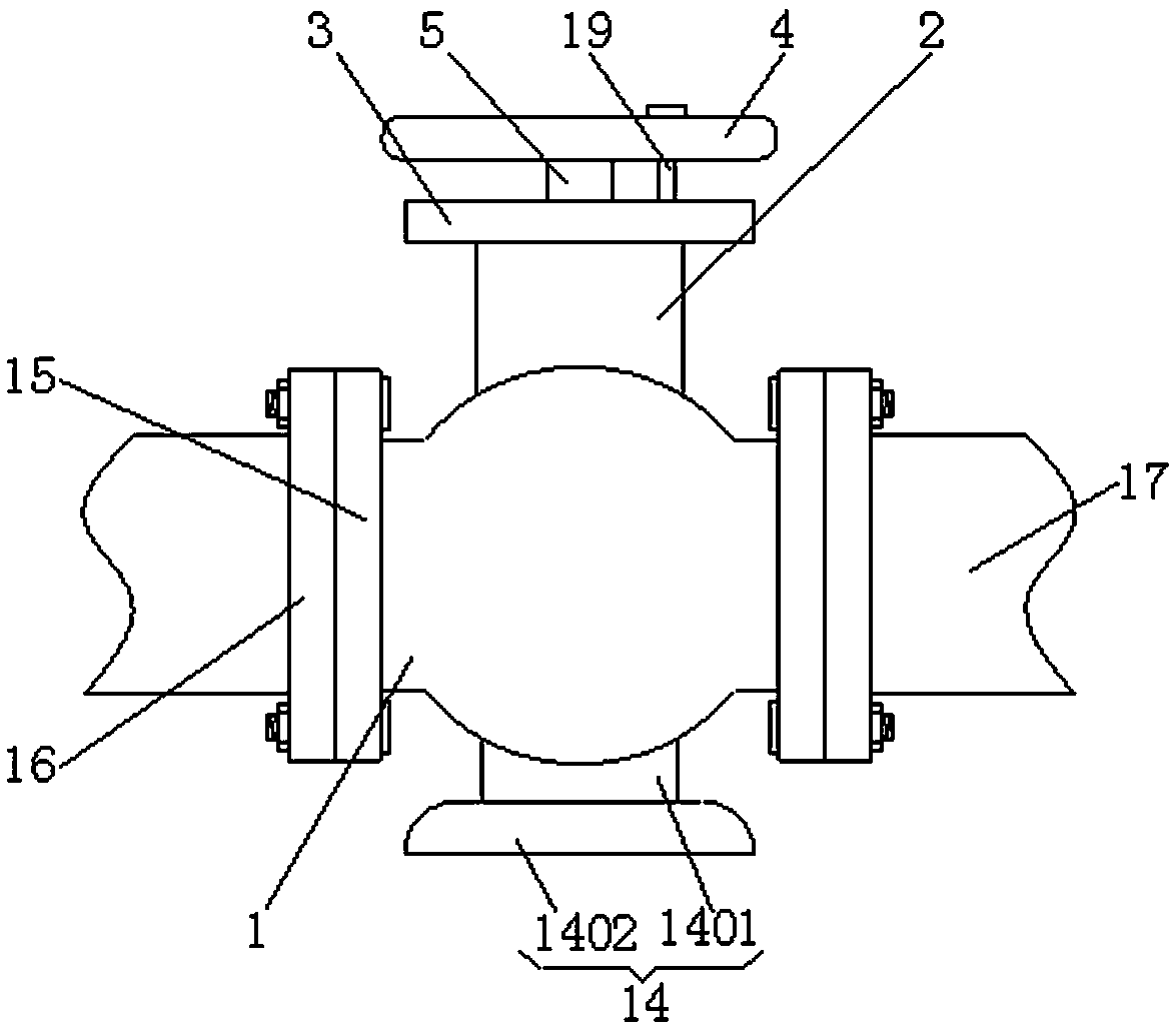
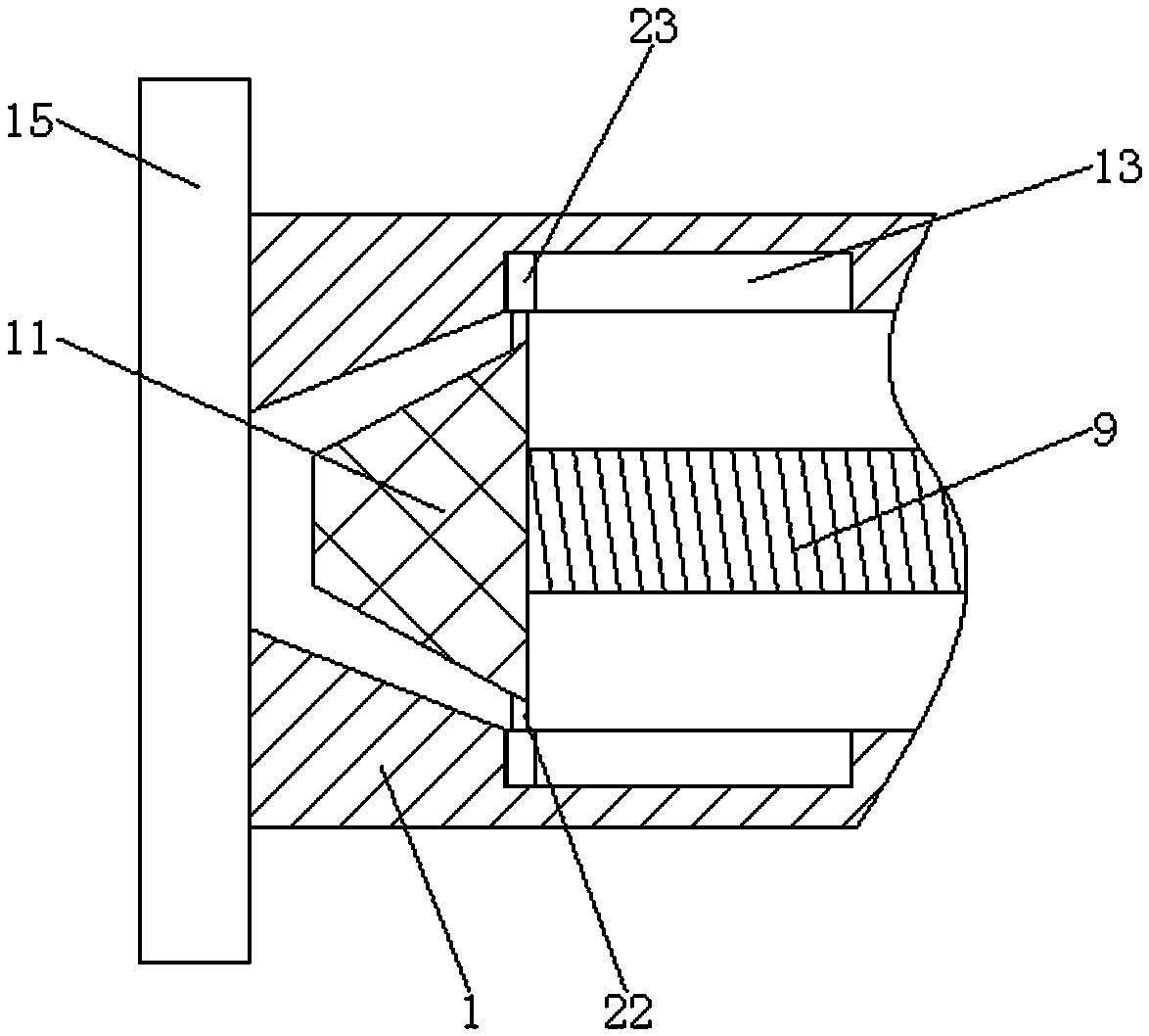
[0027] see Figure 1-6, an industrial pipeline valve, including a valve body 1, the top of the valve body 1 is connected with a positioning pipe 2, the top of the positioning pipe 2 is fixedly connected with a cover plate 3, the top of the cover plate 3 is provided with a turntable 4, and the top of the inner wall of the turntable 4 is provided with Locating bolt 19, the bottom of locating bolt 19 runs through turntable 4 and cover plate 3 in turn and extends ...


PUM


Abstract

The invention discloses an industrial pipeline valve. The industrial pipeline valve comprises a valve body. The top of the valve body communicates with positioning pipes. The tops of the positioning pipes are fixedly connected with a covering plate. A swivel plate is arranged at the top of the covering plate. A rotating rod is fixedly connected to the bottom of the swivel plate. The bottom of theswivel rod sequentially penetrates through the covering plate and the positioning pipe, extends into the valve body, and is fixedly connected with a first helical gear. A positioning rod is fixedly connected to the right sided of the bottom of the inner wall of the valve body. The swivel plate drives the swivel rod to rotate. The swivel rod drives the first helical gear to rotate. The first helical gear drives the second helical gear to rotate through meshing of teeth. The second helical gear drives a threaded rod to rotate. The threaded rod drives a flow adjusting block to move left and rightthrough a thread on the surface and a thread in a threaded hole. The flow adjusting block moves leftwards and rightwards to adjust flow volume, and therefore the effect of adjusting flow is achieved.

Description

technical field [0001] The invention relates to the technical field of industrial valves, in particular to industrial pipeline valves. Background technique [0002] Industrial valves are important accessories for controlling the flow of media on industrial pipelines. They can be used to control the flow of various types of fluids such as air, water, steam, various corrosive media, mud, oil, liquid metal and radioactive media. The valve is composed of three parts: the valve body, the opening and closing mechanism, and the valve cover. This time we will focus on the structural characteristics of the commonly used valves in our company and the precautions for correct use. [0003] Industrial pipeline valves are a kind of industrial valves, but the existing industrial pipeline valves do not have the function of adjusting the flow rate, and cannot adjust the flow rate, so that users cannot accurately control the flow rate of industrial pipeline valves during use, thus wasting a l...

Claims


Application Information

Patent Timeline
Patent Type & Authority Applications(China)
IPC IPC(8): F16K1/38F16K31/53
CPCF16K1/38F16K31/53
Inventor 康毛娣
Owner 康毛娣
Why Eureka
Try Eureka