Micro pump using ferrofluid or magneto-rheological fluid

a technology of ferrofluid and magnetorheological fluid, which is applied in the direction of piston pumps, positive displacement liquid engines, liquid fuel engines, etc., can solve the problems of loss of fluid pressure, fatigue at the valve connector end, and gradual wear of valves and moving parts, so as to improve flow and pump efficiency

Inactive Publication Date: 2005-03-31
IND TECH RES INST
View PDF3 Cites 17 Cited by
  • Summary
  • Abstract
  • Description
  • Claims
  • Application Information

AI Technical Summary

Benefits of technology

[0009] The primary objective of the present invention is to provide a micro pump using ferrofluid or megneto-rheological fluid, which micro pump improves flow and pump efficiency.

Problems solved by technology

However, after a long-term use, the valves and moving parts are gradually worn out to lose their reliability, even causing fatigue at valve connector ends in some cases.
Such valve design may eventually lead to loss of the fluid pressure, which in turn reduces flow to be driven by the pump or causes contamination due to back flow of the working fluid.
Although the design is free from problems associated with the above mentioned valves and moving parts, deformation level of the piezoelectric piece 86 is limited by its material characteristics, so the output flow is consequently limited.
Thus, it is difficult to satisfy the commercial need with the valve-less micro pump 85.
Also, back flow may occur to reduce efficiency in driving the working fluid and cause contamination of the working fluid when the micro pump of the above design is operated.
However, despite of efficiency in terms of driving the working fluid, serious contamination problem caused by mixing the working fluid 91 and the ferro-magnetic fluid 92 is not taken into account in designing this micro pump.
While the micro pump of such design is operated as such, the working fluid 91 to be discharged clearly does not fulfill such requirement, and the contamination problem gets worse as the operation time gets longer, making such design unpractical in terms of fulfilling the industrial demand.

Method used


Image

  • Micro pump using ferrofluid or magneto-rheological fluid
  • Micro pump using ferrofluid or magneto-rheological fluid
  • Micro pump using ferrofluid or magneto-rheological fluid

Examples


first embodiment

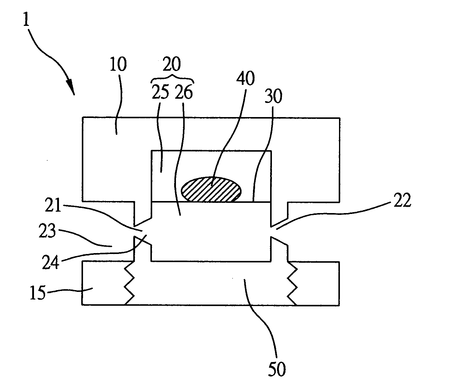
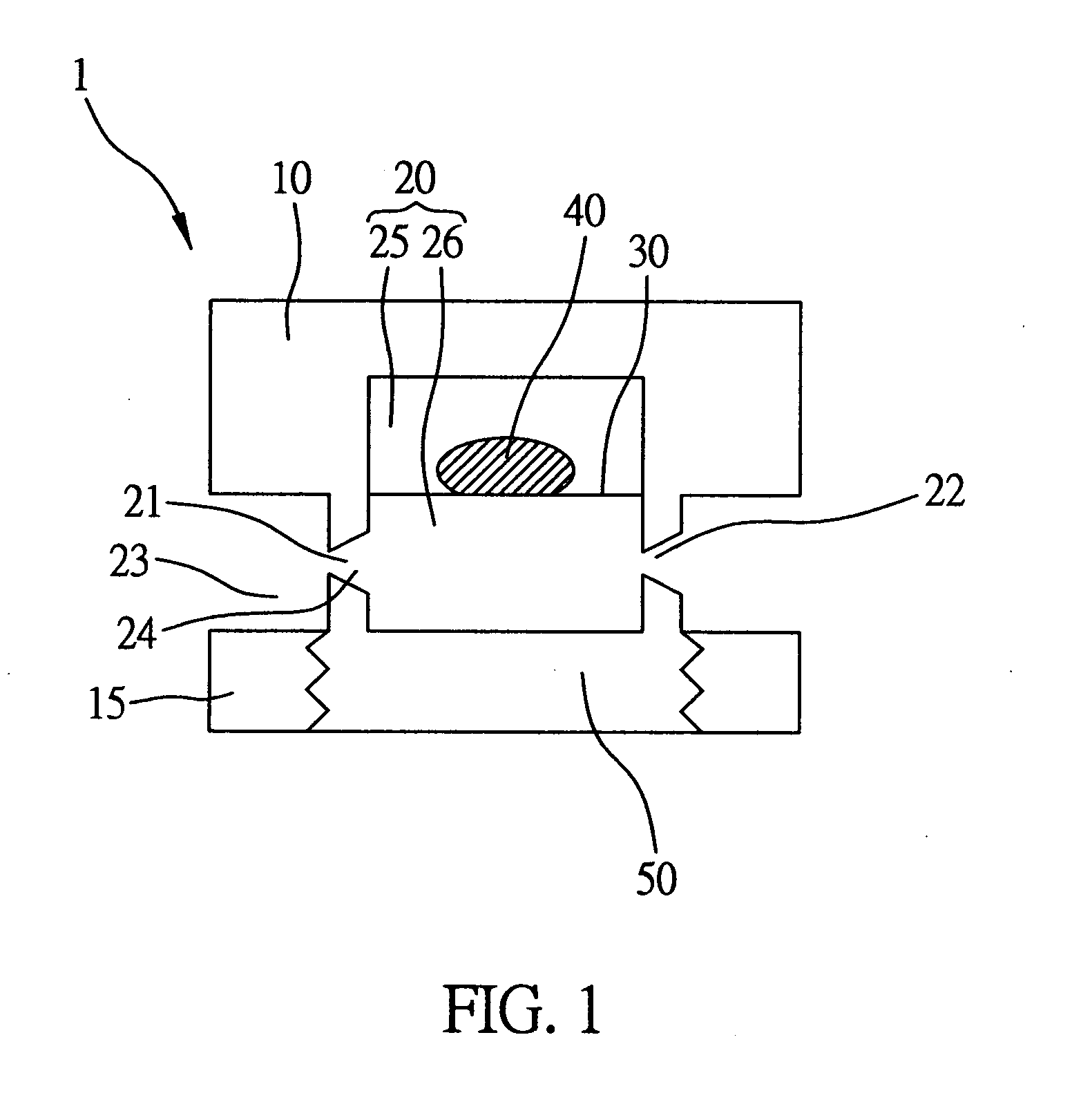
[0043] According to the present invention, a micro pump using ferro-fluid / magneto-rheological fluid is fabricated in the microelectromechanical (MEM) process and comprises a plurality of micro pump components assembled together. FIG. 1 is a cross-sectional view of a micro pump according to the present invention. Referring to FIG. 1, a silicon substrate body comprising a first body 10 and a second body 15 is provided such that an accommodating space 20 within the silicon substrate body is formed from recess portions of the first and second bodies 10 and 15. Two openings are formed at the junction gaps between the two bodies 10 and 15 to serve as an entrance 21 and an exit 22 for a working fluid on two corresponding sides of the accommodating space 20. A polydimethylisiloxane (PDMS) membrane 30 is formed in the accommodating space and located above the entrance 21 and the exit 22 to separate the accommodating space 20 into a first space 25 and a second space 26. As a result, the entra...

second embodiment

[0054] Therefore, the movable magnets 56 on the top lid 55 serve as a driving source for the micro pump of the As shown in FIGS. 6A and 6B, the two movable magnets 56 move to the center of the top lid 55 to drive two corresponding ferro-fluid / magneto-rheological fluid units 70 to shift until they approach to each other. The working fluid in the accommodating space is then squeezed by the two ferro-fluid / magneto-rheological fluid units 70, so that output of the working fluid via the exit 62 is greater than input of the working fluid via the entrance 61, and the micro pump performs a pump mode operation. On the other hand, when the movable magnets 56 are driven to repel from each other until they return to two corresponding sides of the top lid 55, the input of the working fluid via the entrance 61 is greater than the output of the working fluid via the exit 62 due to a pressure drop in the accommodating space 65. And the micro pump performs a supply mode operation to complete one pu...


PUM


Abstract

A micro pump using a ferro-fluid/magneto-rheological fluid to drive a working fluid is proposed. The micro pump has a body with an accommodating space and an opening that communicates with the accommodating space. A ferro-fluid/magneto-rheological fluid and a magnetic field generating unit are disposed on the body. As the ferro-fluid/magneto-rheological fluid is attracted to the magnetic field after being magnetized, the ferro-fluid/magneto-rheological fluid is deformed or shifted to drive the working fluid, so as to control the working fluid to flow in and out of the accommodating space. Accordingly, the pump is improved for its efficiency and precision to control the flow while the back flow of the working fluid is prevented.

Description

BACKGROUND OF THE INVENTION [0001] 1. Field of the Invention [0002] The invention relates to a micro pump using ferrofluid or magneto-rheological fluid, and more particularly, to a micro pump that improves flow and pump efficiency. [0003] 2. Description of the Related Art [0004] The micro fluid control device fabricated by microelectromechanical system (MEMS) technology is characterized by having a small size, precise flow control, and fast reaction time. As the micro fluid control device can be integrated with the conventional micro sensor on the same system for a feedback control, a large batch of the micro fluid control devices may be manufactured. Therefore, the micro fluid device has become one device that is worth of researches and widely implemented in the industry. [0005] For a micro pump component in the micro fluid control device, its related technology has been developed to a matured stage, so the micro pump component has been applied to different fields, such as chemical...

Claims


Application Information

Patent Timeline
Patent Type & Authority Applications(United States)
IPC IPC(8): F04B7/00F04B19/00F04B43/04F04B53/10
CPCF04B7/003F04B7/0038F04B53/1077F04B43/043F04B19/006
Inventor LU, MING-CHANGWANG, CHI-CHUANLIU, MIN-SHENG
Owner IND TECH RES INST
Why Eureka
Try Eureka