Scanning mirror and laser radar

A technology of scanning mirrors and mirrors, applied in the field of scanning mirrors, can solve the problems of difficult performance, limited application of solid-state laser radar, and large volume.

Pending Publication Date: 2019-04-02
北京觉醒纪科技有限公司
View PDF0 Cites 10 Cited by
  • Summary
  • Abstract
  • Description
  • Claims
  • Application Information

AI Technical Summary

Problems solved by technology

For example, solid-state lidar uses MEMS two-dimensional scanning mirror to scan laser, which has the advantages of compact structure and fast scanning speed, but limited by the constraints of semiconductor technology, the cost of MEMS scanning mirror is very high, which limits the application of solid-state lidar
Multi-line laser radar uses multiple lasers arranged in a row in the vertical direction, and uses a rotating structure to rotate multiple lasers to realize scanning in the horizontal direction. Although this structure can reduce costs, it has the disadvantages of large volume and limited wiring harness. problems, its performance is difficult to meet the growing demand

Method used


Image

  • Scanning mirror and laser radar
  • Scanning mirror and laser radar
  • Scanning mirror and laser radar

Examples


Embodiment Construction

[0064] The invention is described below with reference to various embodiments and with reference to the accompanying drawings. While this invention has been described in terms of the best mode for carrying out its objectives, those skilled in the art will appreciate that various modifications may be made in light of these teachings without departing from the spirit or scope of the invention.

[0065] overview

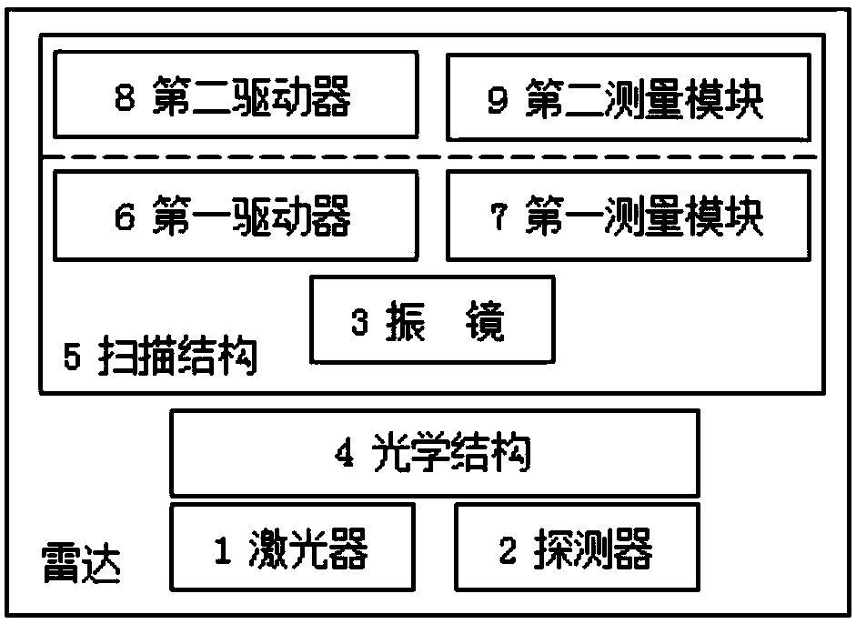
[0066] figure 1 A block diagram of a radar according to the present invention is shown. The radar includes a laser 1 and a detector 2. The laser 1 continuously emits pulsed laser light at a specific frequency (for example, 125kHz), and its wavelength is, for example, 905nm. The emitted light is projected to an object (for example, a building, a pedestrian, a vehicle, a traffic sign, etc.) located at a certain distance, and reflected light is generated. The detector 2 can receive this reflected light. By measuring the time difference Δt between sending out the lase...


PUM


Abstract

The invention provides a scanning mirror. The scanning mirror comprises a reflecting mirror reflecting a light beam and an elastic sheet, wherein the elastic sheet comprises a frame part and a vibrating part, the vibrating part is elastically connected to the frame part through a connection part and is attached to the reflecting mirror, the vibrating part drives the reflecting mirror to rotate around a transverse shaft in a reciprocating manner relative to the frame part, so as to scan light beams in a direction vertical to the transverse shaft. Through adoption of the scanning mirror, a single scanning mirror is used for reflecting the same light beam at different scanning angles, so as to form multiple scanning light beams of different angles, therefore, a scanning effect of approximatemulti-line laser radar is achieved, and the cost is lowered remarkably. Further, the invention provides a laser radar comprising the scanning mirror. The laser radar is low-cost and is small in volumebut has high performance.

Description

technical field [0001] This application relates to scanning mirrors, and in particular to a one-dimensional mechanical galvanometer for scanning beams, and a lidar incorporating such a galvanometer. Background technique [0002] Vehicles may be configured to operate in an autonomous mode, where the vehicle navigates through an environment with little or no driver intervention. Such autonomous vehicles may include one or more sensors, such as lidar, configured to detect information about the environment surrounding the vehicle. [0003] Lidar has a laser and a detector. The detector can detect the laser light emitted by the laser and reflected by the reflective object. By measuring the flight time of the laser light, the distance of the reflective object can be determined. By scanning a certain area quickly and repeatedly with lidar, continuous real-time information on the distances of all reflective objects in the area can be obtained. Combining distance, laser orientation...

Claims


Application Information

Patent Timeline
Patent Type & Authority Applications(China)
IPC IPC(8): G01S17/93G01S7/481
CPCG01S7/4817G01S17/931
Inventor 陈泽
Owner 北京觉醒纪科技有限公司
Why Eureka
Try Eureka