
A cantilever type supporting structure design method based on deformation control

A support structure and deformation control technology, which is applied in the field of cantilever support structure design based on deformation control, can solve the problems that the soil cannot fully reach the limit earth pressure state, and the influence of the internal force of the support structure cannot be considered. The effect of popularizing application value, simple and feasible calculation method, and saving project cost

Active Publication Date: 2019-04-02
EAST CHINA JIAOTONG UNIVERSITY
View PDF6 Cites 3 Cited by
  • Summary
  • Abstract
  • Description
  • Claims
  • Application Information

AI Technical Summary

Problems solved by technology

[0003] However, the existing support structure design methods are mostly based on the limit equilibrium method. This method calculates the internal force of the support structure under the assumption that the soil before and after the pile reaches the limit earth pressure state, and cannot consider the impact of the deformation of the support structure on the pile. However, in the actual foundation pit engineering, the deformation limit of the support structure is usually relatively strict, and the soil before and after the pile often cannot fully reach the limit earth pressure state

Method used


Image

  • A cantilever type supporting structure design method based on deformation control
  • A cantilever type supporting structure design method based on deformation control
  • A cantilever type supporting structure design method based on deformation control

Examples


Embodiment Construction

[0044] In order to facilitate the understanding of the present invention, the present invention will be described more fully below with reference to the associated drawings. Several embodiments of the invention are shown in the drawings. However, the present invention can be embodied in many different forms and is not limited to the embodiments described herein. Rather, these embodiments are provided so that the disclosure of the present invention will be thorough and complete.

[0045] Unless otherwise defined, all technical and scientific terms used herein have the same meaning as commonly understood by one of ordinary skill in the technical field of the invention. The terms used herein in the description of the present invention are for the purpose of describing specific embodiments only, and are not intended to limit the present invention. As used herein, the term "and / or" includes any and all combinations of one or more of the associated listed items.

[0046] see fig...


PUM


Abstract

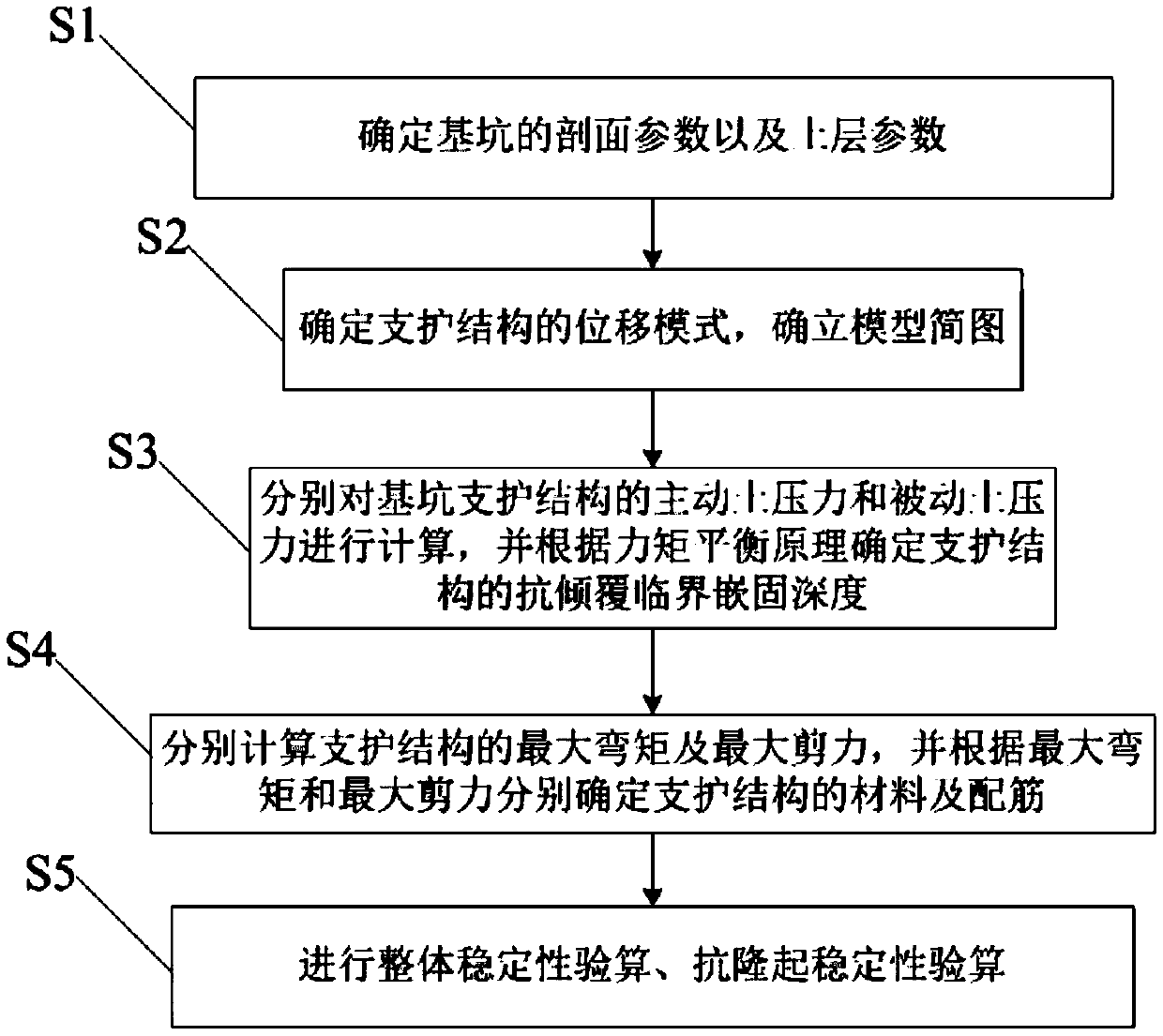
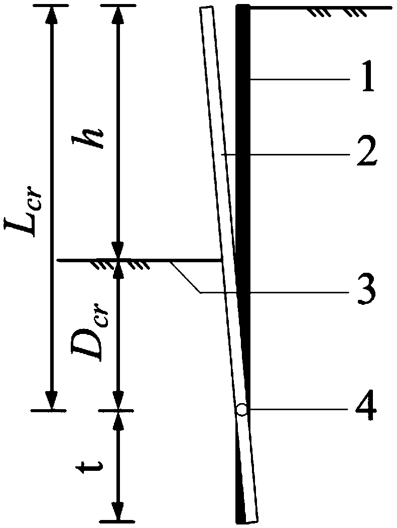
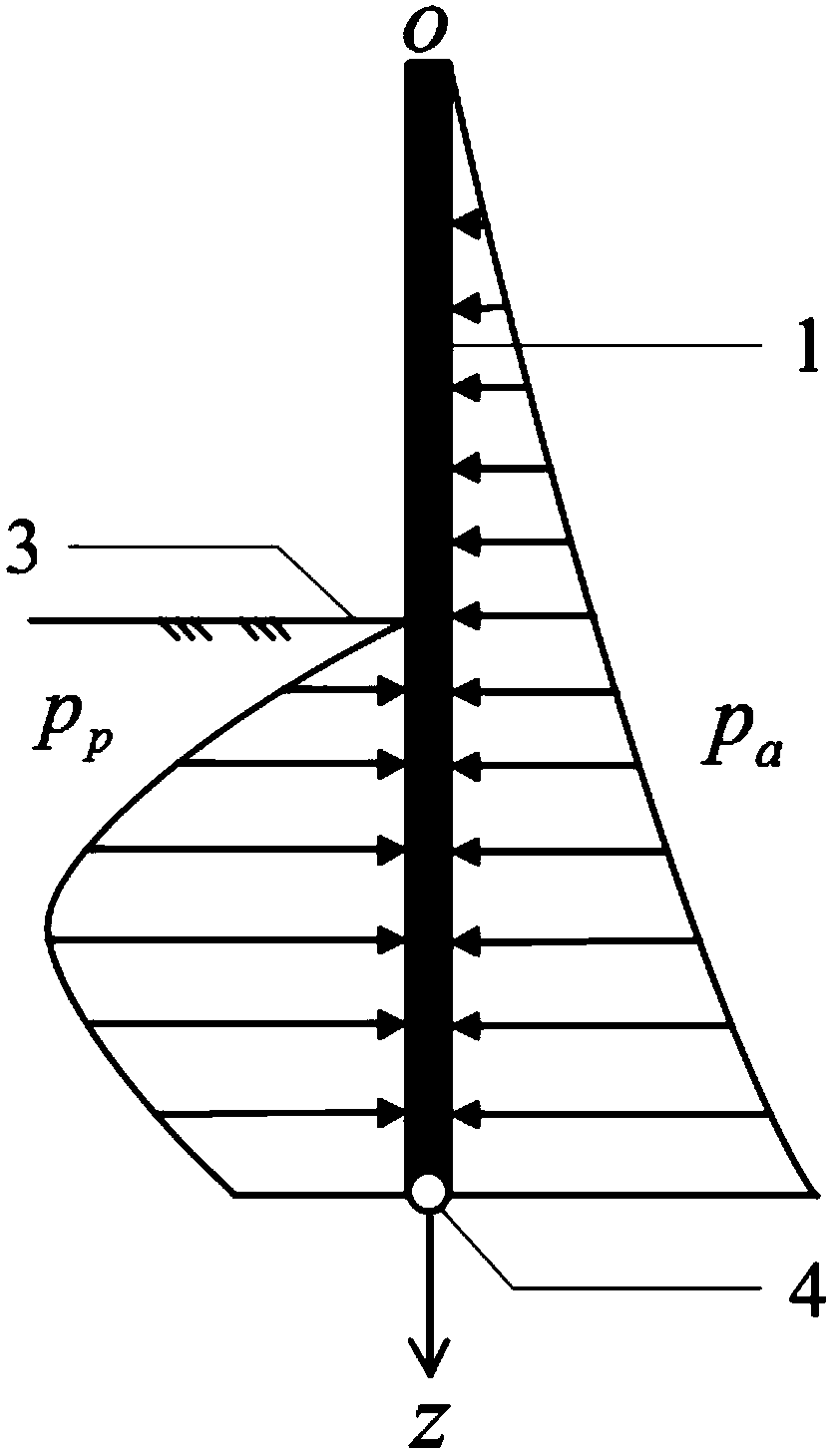
The invention provides a cantilever type supporting structure design method based on deformation control. The cantilever type supporting structure design method comprises the steps of S1 determining the section parameters of a foundation pit and physical and mechanical parameters of a soil body; S2 determining a displacement mode of the support structure, and determining a model sketch; S3 calculating the active soil pressure and the driven soil pressure of the foundation pit supporting structure respectively, and determining the anti-overturning critical embedding depth of the supporting structure according to the moment balance principle; S4 calculating the maximum bending moment and the maximum shearing force of the supporting structure respectively, and determining the materials and reinforcing bars of the supporting structure according to the maximum bending moment and the maximum shearing force respectively; and S5 carrying out overall stability checking calculation and uplift resistance stability checking calculation. The method overcomes the defect that deformation of the supporting structure cannot be considered in a conventional foundation pit design method, the design calculation is controlled through the deformation degree of the cantilever type supporting structure, the calculation method is simple and feasible, the construction cost can be effectively saved and the construction amount can be effectively reduced on the premise that safety is ensured, and the method has good application and popularization value.

Description

technical field [0001] The invention relates to the technical field of civil engineering construction, in particular to a design method of a cantilever support structure based on deformation control. Background technique [0002] With the further advancement of our country's capital construction projects, the theoretical level of foundation pit engineering design has also been greatly developed, and the traditional method of design according to bearing capacity is gradually transitioning to design according to deformation control. [0003] However, the existing support structure design methods are mostly based on the limit equilibrium method. This method calculates the internal force of the support structure under the assumption that the soil before and after the pile reaches the limit earth pressure state, and cannot consider the deformation of the support structure. However, in actual foundation pit engineering, the deformation limit of the support structure is usually rel...

Claims


Application Information

Patent Timeline
IPC IPC(8): G06F17/50E02D17/04
CPCE02D17/04G06F30/20G06F30/13G06F2119/06
Inventor 徐长节范晓真胡国明胡琦刘俊岩刘兴旺
Owner EAST CHINA JIAOTONG UNIVERSITY
Learn More