Universal change-over switch

A transfer switch and universal technology, applied in electrical switches, electrical components, circuits, etc., can solve the problems that the universal transfer switch cannot indicate the internal on-off condition, the impact of installation efficiency, and hidden safety hazards, so as to ensure compactness, improve The effect of reducing efficiency and assembly difficulty

Pending Publication Date: 2019-04-02
ZHEJIANG CHINT ELECTRIC CO LTD +1
View PDF7 Cites 0 Cited by
  • Summary
  • Abstract
  • Description
  • Claims
  • Application Information

AI Technical Summary

Problems solved by technology

[0003] However, the existing universal transfer switch cannot indicate the internal on-off situation, and the on-off situation in the switch cannot be observed from the outside. It is necessary to consult the drawings, instructions, or use tools such as multimeters and buzzers to perform on-site measurements before wiring. Due to the particularity of the transfer switch, few manufacturers can provide on-off drawings of all products, which seriously affects the installation efficiency. If the wiring is wrong, it will leave a safety hazard to customers.

Method used


Image

  • Universal change-over switch
  • Universal change-over switch
  • Universal change-over switch

Examples


Embodiment approach

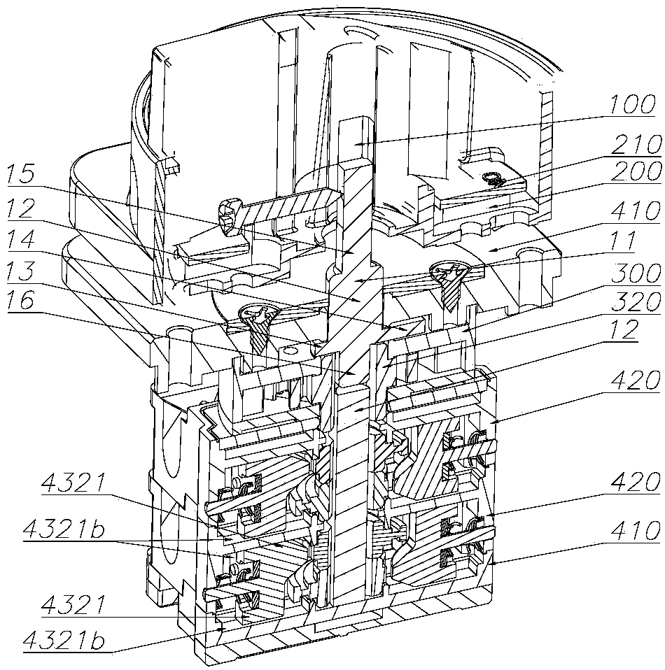
[0057] Such as Figure 10-12 An embodiment of the positioning mechanism 300 is shown, the positioning mechanism 300 includes a positioning base 310 and a positioning cover 312, and a positioning ratchet 320 arranged in the middle of the positioning base 310 and connected to the main shaft 1, at the center of the positioning ratchet 320 Around the center of the axis of the positioning ratchet 320, a positioning catch 330 is symmetrically arranged. The positioning catch 330 is connected with the positioning base 310 through a catch spring 340. Slot 321, the detent spring 340 drives the positioning detent 330 to move into the detent positioning groove 321, and the positioning detent 330 pushes the positioning ratchet 320, so that the positioning ratchet 320 meets a certain angle when rotating, so as to ensure that the main shaft 1 can drive the contact module 420 Travel enough.

[0058] Further, one side of the positioning detent 330 cooperates with the positioning ratchet 320, ...


PUM


Abstract

A universal change-over switch includes a main shaft and a contact module connected to the main shaft, the contact module includes a contact base and a cam module disposed in the contact base to cooperate with the main shaft, multiple sets of contact mechanisms linked with the cam module are arranged around the cam module, the supports of the contact mechanisms can be movably arranged in the contact base to cooperate with the cam module, moving contacts are arranged on the supports to cooperate with fixed contacts, indication rods are arranged on the supports, the contact base is provided withindication holes cooperated with the indication rods, the supports fixing the moving contacts are provided with the indication rods extended out of the contact base with no need for addition of extramechanisms, the structures of the supports themselves can be directly used to visually indicate the on-off states in the contact module, the indication holes on the contact base are cooperated with the indication rods, so that the guide and location effects can be supplied to the supports when the contact mechanisms are assembled, the assembling difficulty is reduced, and the assembling efficiency is improved.

Description

technical field [0001] The invention relates to the field of low-voltage electrical appliances, in particular to a universal transfer switch. Background technique [0002] The universal transfer switch is a multi-level, multi-circuit control master electrical appliance, which is mainly used for the conversion of various control circuits, the remote control and conversion of power distribution device circuits, the commutation measurement control of voltmeters and ammeters, and can also be used for Directly control small-capacity motors, etc., with the advantages of multi-contact, multi-position, flexible operation, and convenient installation. [0003] However, the existing universal transfer switch cannot indicate the internal on-off situation, and the on-off situation in the switch cannot be observed from the outside. It is necessary to consult the drawings, instructions, or use tools such as multimeters and buzzers to perform on-site measurements before wiring. Due to the...

Claims


Application Information

Patent Timeline
Patent Type & Authority Applications(China)
IPC IPC(8): H01H9/16H01H3/32H01H3/42H01H3/34
CPCH01H3/32H01H3/34H01H3/42H01H9/16
Inventor 付亮鲁君井晓任
Owner ZHEJIANG CHINT ELECTRIC CO LTD
Why Eureka
Try Eureka