
Split stator core mounting and fixing structure and fixing method

A stator core and fixed structure technology, which is applied in the field of split stator core installation and fixed structure, can solve the problems of difficult control of stator core precision and rigidity, high requirements for products and equipment, increased compression and welding processes, etc. , to achieve the effect of low manufacturing cost, high production efficiency and simple production equipment

Pending Publication Date: 2019-04-02
宁波菲仕自动化技术有限公司
View PDF0 Cites 4 Cited by
  • Summary
  • Abstract
  • Description
  • Claims
  • Application Information

AI Technical Summary

Problems solved by technology

Although ordinary split-type stator punching improves material utilization and reduces mold development costs, it can be produced by small-tonnage high-speed punching machines; however, split-type stator punching adds iron core splicing, compression and welding processes, through The above process realizes the fixation of the split stator core; especially the core welding process has high requirements for products and equipment, and the accuracy and rigidity of the stator core are difficult to control, and the production efficiency is not high

Method used


Image

  • Split stator core mounting and fixing structure and fixing method
  • Split stator core mounting and fixing structure and fixing method
  • Split stator core mounting and fixing structure and fixing method

Examples


Embodiment Construction

[0029] According to Figure 1 to Figure 5 The specific implementation of the present invention is further explained:

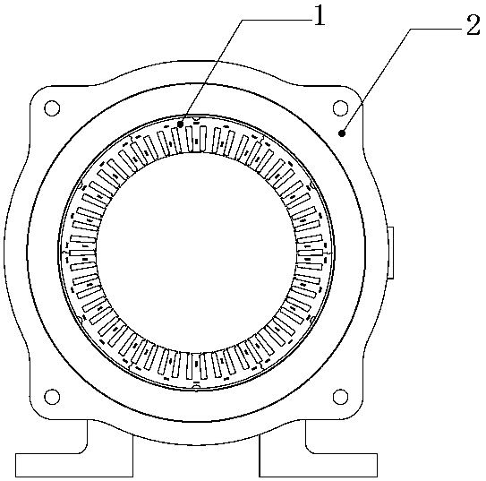
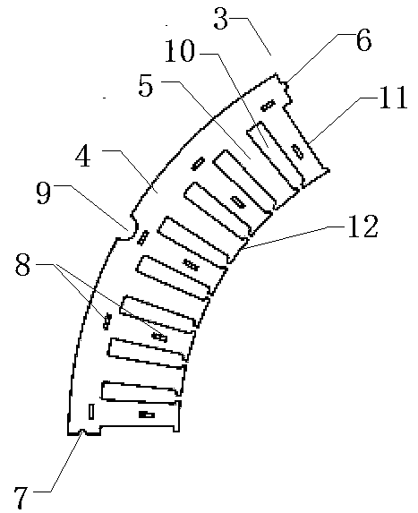
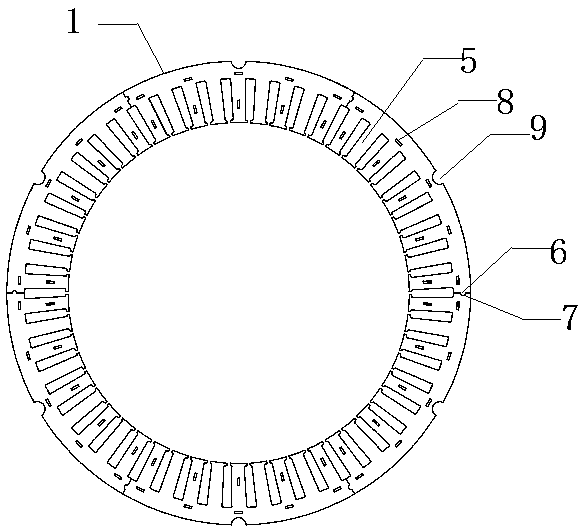
[0030] See figure 1 , A split stator core mounting and fixing structure, comprising a stator housing 2 and a full circle stator core 1. The structure of the full circle stator core 1 is as follows image 3 As shown, a plurality of split stator cores 3 are spliced ​​together, see figure 2 , The split stator core 3 includes a plurality of stator split punches, the stator split punches include an arc-shaped yoke 4 and a number of notch teeth 5 evenly distributed on the inner ring of the yoke 4, A notch 10 is formed between two adjacent notch teeth 5, one end of the yoke 4 is provided with a process groove 7, and the other end is provided with a process boss 6 that matches the process groove 7. The outer ring of the part 4 is provided with a positioning groove 9, and the surfaces of the yoke part 4 and the notch tooth 5 are provided with a plurality of self-fastenin...


PUM


Abstract

The invention discloses a split stator core mounting and fixing structure and a fixing method. The structure comprises a stator casing and a full-circular stator core. The full-circular stator core comprises a plurality of split stator cores. Each split stator iron includes a plurality of stator split punches. Each stator split punch includes a yoke portion and a plurality of slot teeth distributed on the inner ring of the yoke portion. The yoke portion is provided with a process groove at one end, and is provided with a process boss at the other end. The outer ring of the yoke portion is provided with a positioning groove. The plurality of stator split punches are mutually riveted by a self-buckling point to form the split stator core. The plurality of split stator cores are spliced intothe full-circular stator core. The inner wall of the stator casing is provided with a positioning boss. The stator casing sleeves the full-circular stator core and the positioning boss is embedded inthe positioning groove on the full-circular stator core. The structure does not need welding forming, does not has high requirements for the dimensional accuracy and rigidity of the split stator core,is convenient in process control, and has high production efficiency, simple production equipment and low manufacturing cost.

Description

Technical field [0001] The invention relates to the technical field of motors, in particular to a split stator core installation and fixing structure and a fixing method. Background technique [0002] When designing the motor, according to the performance and cost factors of the motor, different specifications of materials are selected for the stator punch and the rotor punch, so that the stator and rotor cannot be manufactured by the punching punch method. The use of split stator punches will be a development direction for servo motors and new energy motors in the future. Although the ordinary split stator punch increases the material utilization rate and reduces the mold development cost, it can be produced by a small tonnage high-speed punch; but the split stator punch increases the core splicing, pressing and welding processes. The above process realizes the fixation of the split stator iron core; especially the iron core welding process has higher requirements on products a...

Claims


Application Information

Patent Timeline
IPC IPC(8): H02K1/14
CPCH02K1/148
Inventor 安高峰冯钰卿刘小林左晓霞王奇辉
Owner 宁波菲仕自动化技术有限公司
Learn More