Broken nail taking-out device of orthopaedic hollow nail

A technology for removing a device and a hollow nail, which is applied in the field of medical devices, can solve the problems of inability to rotate, inconvenient to use, occupying space, etc., and achieves the effects of improving the quality and efficiency of removing broken nails, simple and convenient use and operation, and reasonable structural design.

Pending Publication Date: 2019-04-05
莒县人民医院
View PDF1 Cites 1 Cited by
  • Summary
  • Abstract
  • Description
  • Claims
  • Application Information

AI Technical Summary

Problems solved by technology

However, the hollow nail often cannot be rotated during the removal process. The hollow nail is tightly combined with the bone, causing the hollow nail to break and damage. It is difficult to remove it with the removal tool equipped with the hollow nail. At this time, the traditional method generally uses a large pliers extractor. , but the use of forceps is more destructive to bone and brings pain to patients;
[0003] In the prior art, Patent Application No. 201711119647.6 discloses a device for taking out orthopedic hollow nails. It uses an electric drill to drive the perforated nail to drill an internal thread on the broken nail, and then screw the broken nail into the broken nail by taking the nail to remove the broken nail. The nails are taken out, but the connection between the punching nail and the nail taking device of this device takes up space, and there are many inconveniences in the actual operation process. hindrance, inconvenient to use; moreover, the above-mentioned device needs a two-step operation of punching first and then taking out the nail when taking out the nail. There are still many problems in the removal of broken hollow nails, which need to be improved urgently

Method used


Image

  • Broken nail taking-out device of orthopaedic hollow nail
  • Broken nail taking-out device of orthopaedic hollow nail
  • Broken nail taking-out device of orthopaedic hollow nail

Examples


Embodiment Construction

[0021] In order to clearly illustrate the technical features of this solution, the present invention will be described in detail below through specific implementation modes and in conjunction with the accompanying drawings.

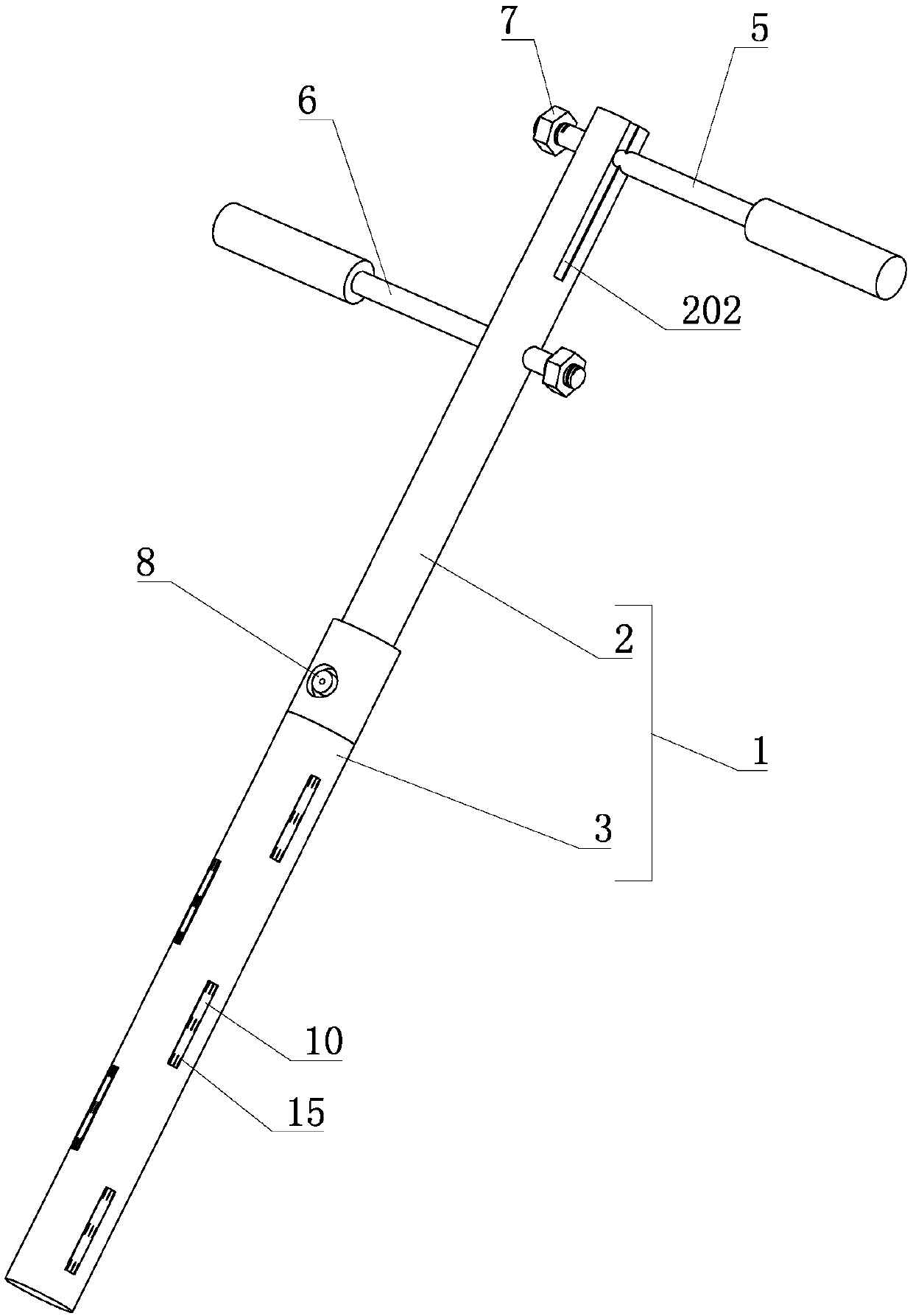
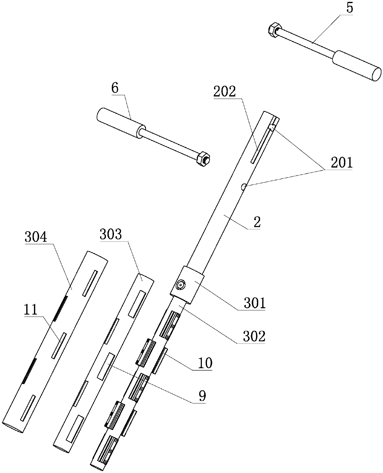
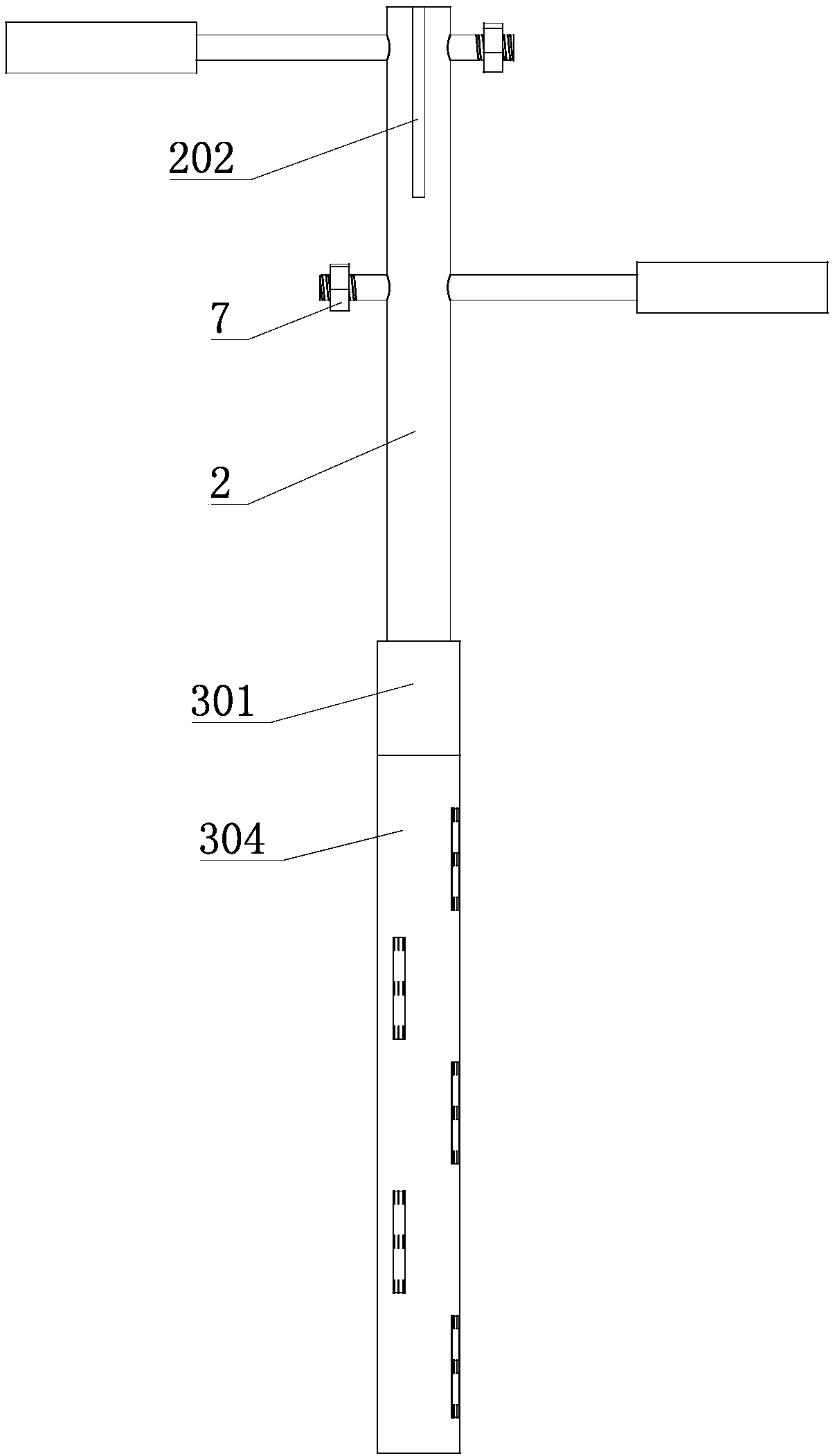
[0022] Such as Figure 1-4 As shown, a broken nail removal device for orthopedic hollow nails includes a screw rod 1, and a hand-held unit is provided on the connecting part 2 of the screw rod 1, and the handheld unit is used for hand holding. The connecting part 2 is fixedly connected with the expansion part 3, and the expansion part 3 is used for inserting into the inside of the broken nail, and the expansion part 3 is provided with an expansion block 4 which can be displaced along the axial direction of the expansion part 3, and the expansion block 4 is outward After expansion, it is connected to the inner wall of the broken nail, so that the broken nail moves with the expansion part 3 and the connecting part 2.

[0023] In order to facilitate the ope...


PUM


Abstract

The invention relates to the field of a medical appliance, in particular to a broken nail taking-out device of an orthopaedic hollow nail. The device comprises a nail taking rod, wherein a handheld unit is arranged on a connecting part of the nail taking rod, and is used for being held by hands; the connecting part is fixedly connected with an expansion part; the expansion part is used for being inserted into the broken nail; an expansion block capable of moving in the axial direction of the expansion part is arranged on the expansion part; the expansion block outwards extends to be connectedwith the inner wall of the broken nail, so that the broken nail moves along with the expansion part and the connecting part. According to the broken nail taking-out device of the orthopaedic hollow nail provided by the invention, the structural design is reasonable; the advanced hole punching on the broken nail is not needed; the broken nail can be directly fixed and is then rotationally taken out; the damage to the bone around the broken nail is basically eliminated; the device is of a rod-shaped structure and can directly extends into the broken nail, so that the use and the operation are simple and convenient; and the broken nail taking-out quality and efficiency of the hollow nail are improved.

Description

technical field [0001] The invention relates to the field of medical instruments, in particular to a device for removing broken orthopedic hollow nails. Background technique [0002] At present, in orthopedic surgery, internal fixation with screws combined with steel plates and hollow nails is a commonly used method, because hollow nails have structural advantages that ordinary screws do not have, so hollow nails are used very frequently. However, the hollow nail often cannot be rotated during the removal process. The hollow nail is tightly combined with the bone, causing the hollow nail to break and damage. It is difficult to remove it with the removal tool equipped with the hollow nail. At this time, the traditional method generally uses a large pliers extractor. , but the use of forceps is more destructive to bone and brings pain to patients; [0003] In the prior art, Patent Application No. 201711119647.6 discloses a device for taking out orthopedic hollow nails. It use...

Claims


Application Information

Patent Timeline
Patent Type & Authority Applications(China)
IPC IPC(8): A61B17/92
CPCA61B17/92A61B2017/924
Inventor 韩小波张宝艳
Owner 莒县人民医院
Why Eureka
Try Eureka