

Cervical vertebra massaging device
A cervical spine and shoulder technology, applied in the field of cervical spine massage devices, can solve problems such as accelerated recovery of massage effects, inability to synchronize shoulder and neck massage, etc., and achieve the effect of improving work efficiency
- Summary
- Abstract
- Description
- Claims
- Application Information
AI Technical Summary
Problems solved by technology
Method used
Image

Examples
specific Embodiment approach 1
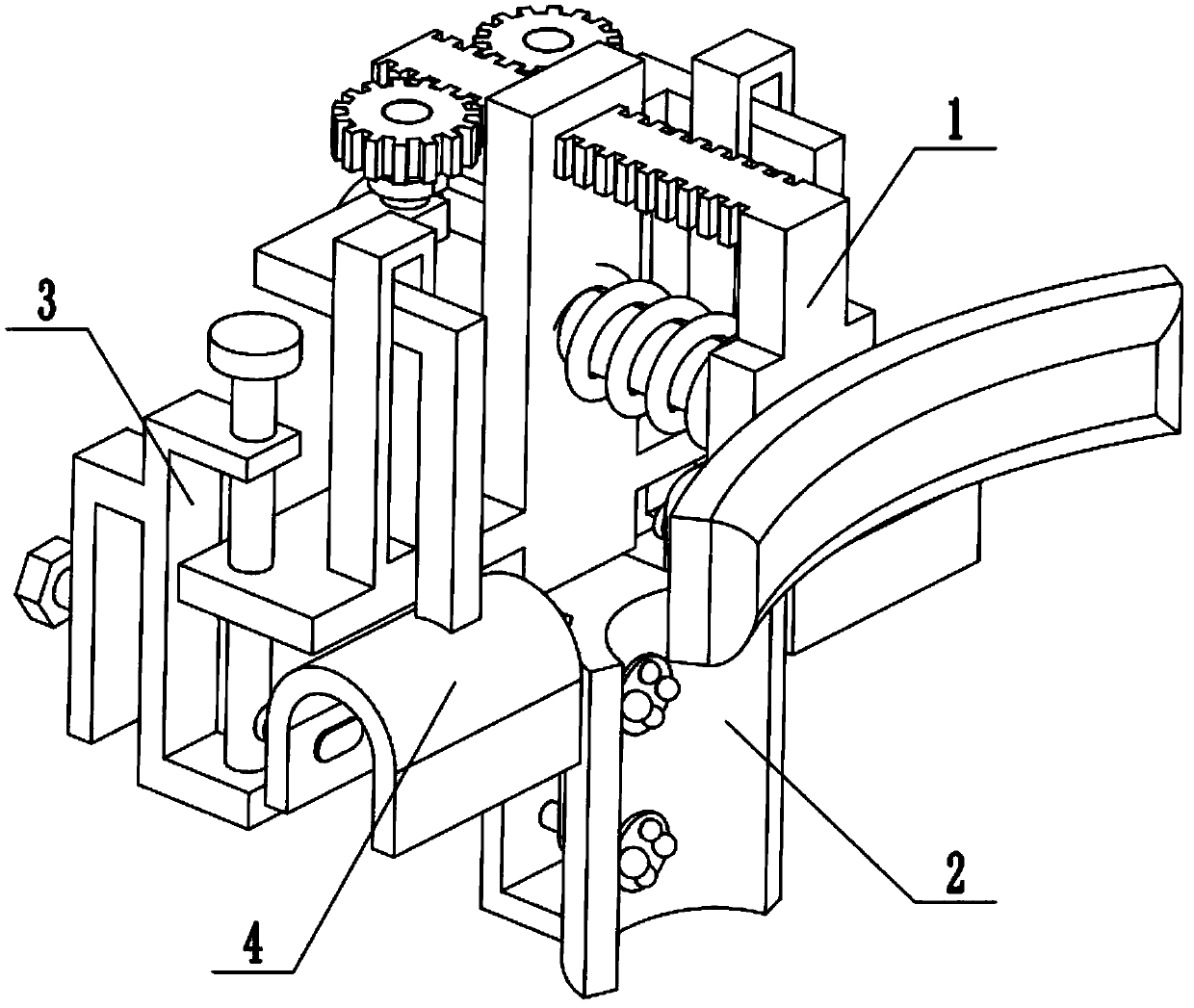
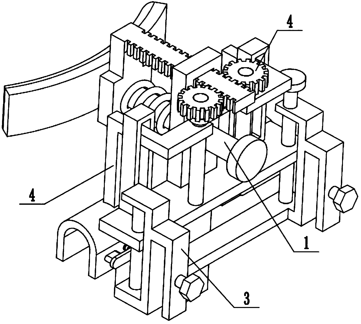
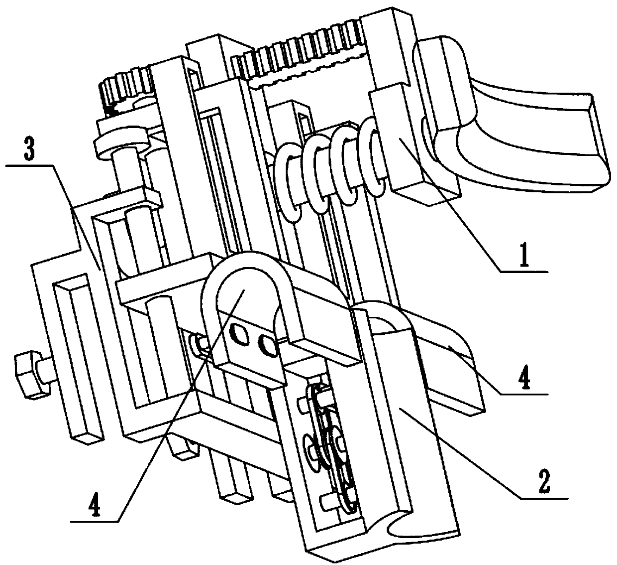
[0027] Combine below Figure 1-9 Description of this embodiment, a cervical spine massage device, including a drive assembly 1, a cervical spine massage assembly 2, an adjustable fixing seat 3 and a shoulder massage device 4, the cervical spine massage assembly 2 is fixedly connected to the lower end of the drive assembly 1, and the drive assembly The rear end of 1 is connected on the adjustment fixing seat 3, and there are two shoulder massage devices 4, the middle ends of the two shoulder massage devices 4 are fixedly connected to the two ends of the drive assembly 1, and the two shoulder massage devices 4 The upper end is meshed with the driving assembly 1 for transmission connection, and the lower ends of the two shoulder massage devices 4 are respectively located at the two ends of the cervical spine massage assembly 2 . When the present invention is in use, the adjustable fixing seat 3 is clamped on the backrest of the stool that the user sits on, and the heights of the ...
specific Embodiment approach 2
[0028] Combine below Figure 1-9 To illustrate this embodiment, the drive assembly 1 includes a sleeve rod slide seat plate 1-1, a spring sleeve rod 1-2, a head arc-shaped pressure plate 1-3, a limit plate 1-4, a spring seat 1-5, Compression spring 1-6, rack 1-7, adjustment plate 1-8 and axle frame plate 1-9; The two ends of -2 are respectively fixedly connected to the head arc-shaped pressure plate 1-3 and the limit plate 1-4, the spring seat 1-5 is fixedly connected to the spring sleeve rod 1-2, and the spring seat 1-5 is located on the sleeve rod slide seat Between the plate 1-1 and the head arc-shaped pressure plate 1-3, the compression spring 1-6 is sleeved on the spring sleeve rod 1-2, and the two ends of the compression spring 1-6 are respectively fixedly connected to the sleeve rod slide seat plate 1 -1 and the spring seat 1-5, the upper end of the spring seat 1-5 is fixedly connected to the rack 1-7, the rack 1-7 is slidably connected to the upper end of the sliding ...
specific Embodiment approach 3
[0029] Combine below Figure 1-9To illustrate this embodiment, the cervical spine massage assembly 2 includes a C-shaped frame 2-1, a neck arc plate 2-2, a motor 2-3, a double groove pulley 2-4, a transmission shaft 2-5, a driven Belt wheel 2-6 and massage disc 2-7; Neck arc plate 2-2 is fixedly connected to the two ends of C-shaped frame 2-1, and C-shaped frame 2-1 is fixedly connected to sleeve rod sliding seat plate 1-1 The bottom surface of the motor 2-3 is fixedly connected to the middle end of the C-shaped frame 2-1, the output shaft of the motor 2-3 is fixedly connected to the double-groove pulley 2-4, and the drive shaft 2-5 is provided with two ends, two One end of the transmission shaft 2-5 is connected to the C-shaped frame 2-1 through bearings with seat rotation respectively, and the other ends of the two transmission shafts 2-5 are connected to the neck arc plate 2-2 in rotation, and the motor 2- 3 is located between the two transmission shafts 2-5, and a driven ...
PUM
 Abstract
Description
Claims
Application Information