Gas-liquid reaction device

A gas-liquid reaction and reaction chamber technology, applied in pH reaction, chemical method of reacting liquid and gas medium, chemical/physical/physical-chemical process, etc. Efficiency and other issues, to achieve the effect of facilitating promotion, promoting the process, and facilitating operation

Inactive Publication Date: 2019-04-05
于兆吉
View PDF0 Cites 0 Cited by
  • Summary
  • Abstract
  • Description
  • Claims
  • Application Information

AI Technical Summary

Problems solved by technology

[0002] The broad understanding of the reaction kettle is a container with physical or chemical reactions. Through the structural design and parameter configuration of the container, the heating, evaporation, cooling and low-speed mixing functions required by the process are realized. A gas-liquid reaction, in order to make it For full reaction, mechanical agitation is usually used, but the use of mechanical agitation in the gas-liquid reaction process has the following disadvantages: mechanical agitation is not conducive to the overall sealing of the reactor, may cause gas overflow, affect the pressure inside the reactor, and cannot control the internal pressure of the reactor. The pressure of the reactor affects the reaction of the materials in the reactor; the gas-liquid reaction efficiency mainly depends on the size of the contact surface between the gas and the liquid, and mechanical stirring has great limitations, which cannot make the gas-liquid contact and mix completely and effectively, thereby reducing the reaction efficiency.

Method used


Image

  • Gas-liquid reaction device

Examples


Embodiment Construction

[0017] The following will clearly and completely describe the technical solutions in the embodiments of the present invention with reference to the accompanying drawings in the embodiments of the present invention. Obviously, the described embodiments are only some, not all, embodiments of the present invention.

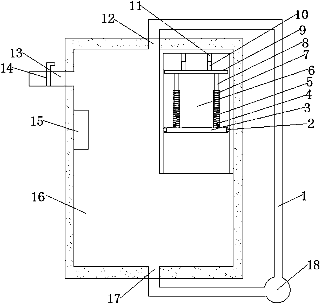
[0018] refer to figure 1 , a gas-liquid reaction device, comprising a reaction chamber 16, the interior of the reaction chamber 16 is a cavity structure, the reaction chamber 16 is equipped with a visual window, the reaction chamber 16 is provided with a liquid level gauge, the reaction chamber The top of 16 is provided with a thermometer for detecting the temperature in the reaction chamber 16, the bottom of the reaction chamber 16 is provided with a liquid outlet 17, the lower end of the liquid outlet 17 is connected with a water pipe channel 1, and a water pump is installed on the water pipe channel 1 18. One end of the water pipe channel 1 is connected with a liq...


PUM


Abstract

The invention discloses a gas-liquid reaction device, which comprises a reaction chamber. A pressure regulation chamber is mounted in the reaction chamber; when internal pressure intensity of the reaction chamber is high, a movable plate is pushed under pressure and moves upwards through spring compression by the aid of slide balls; when the pressure intensity is diminished, the movable plate is pushed to move downwards under the elastic force of springs by the aid of the slide balls, and accordingly the internal pressure intensity of the reaction chamber is kept in a balanced state; when pressurizing is required, electric telescopic rods can be started to extend for pushing the movable plate to move downwards, so that pressurizing can be realized. The reaction chamber is internally provided with a liquid inlet and a liquid outlet, and liquid in the reaction chamber is kept in a flowing state through a water pump; a sprinkler for increasing gas-liquid contact area is mounted at the liquid inlet to promote reaction progress; a changing process of reaction in the reaction chamber can be observed through a visible window. The gas-liquid reaction device is reasonable in design and convenient to operate and popularize.

Description

technical field [0001] The invention relates to the technical field of chemical equipment, in particular to a gas-liquid reaction device. Background technique [0002] The broad understanding of the reaction kettle is a container with physical or chemical reactions. Through the structural design and parameter configuration of the container, the heating, evaporation, cooling and low-speed mixing functions required by the process are realized. A gas-liquid reaction, in order to make it For full reaction, mechanical agitation is usually used, but the use of mechanical agitation in the gas-liquid reaction process has the following disadvantages: mechanical agitation is not conducive to the overall sealing of the reactor, may cause gas overflow, affect the pressure inside the reactor, and cannot control the internal pressure of the reactor. The pressure of the reactor affects the reaction of the materials in the reactor; the gas-liquid reaction efficiency mainly depends on the si...

Claims


Application Information

Patent Timeline
Patent Type & Authority Applications(China)
IPC IPC(8): B01J10/00B01J19/00
CPCB01J10/00B01J19/0013B01J19/0053B01J19/0086
Inventor 于兆吉
Owner 于兆吉
Why Eureka
Try Eureka