
Bearing part assembling automatic equipment

A technology of automation equipment and bearing parts, which is applied in the field of bearing assembly and processing, can solve the problems of large working space, low safety performance, and low work efficiency, and achieve the effects of improving work efficiency, reducing workload, and reducing work space

Inactive Publication Date: 2019-04-05
深圳市诚盈信科技有限公司
View PDF0 Cites 9 Cited by
  • Summary
  • Abstract
  • Description
  • Claims
  • Application Information

AI Technical Summary

Problems solved by technology

[0002] Bearing parts should play an important role in different products and are widely used in many products, such as automobiles, electric drills, bicycles and various processing machinery and equipment. With the progress of the times, the quality of products used And the service life is getting higher and higher, and more products will be applied to bearing parts. In addition, most of the bearing parts on the market are assembled manually, which has low work efficiency, large labor force, low safety performance, and requires a large space for work. higher cost

Method used


Image

  • Bearing part assembling automatic equipment
  • Bearing part assembling automatic equipment
  • Bearing part assembling automatic equipment

Examples


Embodiment 2

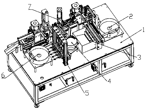
[0028] The second embodiment is different from the above in that a heat dissipation device is arranged inside the workbench 1, and the heat dissipation device is used to dissipate heat from the mechanisms on the workbench 1.

Embodiment 3

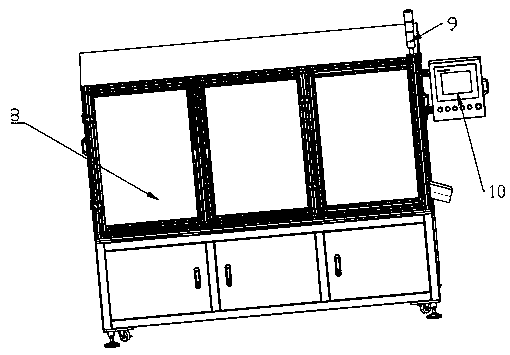
[0029] The third embodiment is different from the above in that an alarm light 9 is installed at the upper end of the protective cover 8 and a controller 10 is installed on the side of the protective cover 8 above the discharge port.

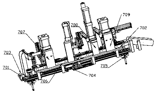
[0030] The working principle of the present invention: firstly, the worker opens the machine through the controller 10, and then opens the side panels through the handle on the protective cover 8, and then puts different materials into the corresponding mechanism in sequence. First, the first oscillation Mechanism 2 works. The inner bearing is transported to the first direct vibration device through the first oscillating disc. The first direct vibration device transports the bearing to the bottom of the first grabbing device at the end, and the first grabbing device grabs the bearing below. Take it into the mold on the second moving rail 702. When the mold moves to the next station, the axis mechanism 3 starts to work, and the lifting cylinder trans...


PUM


Abstract

The invention discloses bearing part assembling automatic equipment. The bearing part assembling automatic equipment comprises a workbench and a protective cover, and the protective cover is arrangedon the workbench; a first oscillation mechanism, a spindle mechanism, a feeding mechanism, a spindle sleeve mechanism, a second oscillation mechanism and a moving mechanism are all fixed to the workbench; the moving mechanism is fixed to the left side of the workbench; the first oscillation mechanism, the spindle mechanism, the spindle sleeve mechanism, the feeding mechanism and the second oscillation mechanism are sequentially arranged on the side face of the moving mechanism from the working end to the finish end; the first oscillation mechanism is used for conveying an inner bearing to themoving mechanism; the spindle mechanism is used for conveying a spindle to the moving mechanism; the spindle sleeve mechanism is used for conveying a spindle sleeve to the moving mechanism; the feeding mechanism is used for conveying an outer bearing to the moving mechanism; and the second oscillation mechanism is used for conveying a clamp spring to the moving mechanism. Therefore, the cost is reduced, the working space is reduced, the working efficiency is improved, and the bearing part assembling automatic equipment is a very good product and has the good market application value.

Description

Technical field [0001] The invention relates to the field of assembly processing of bearing parts, in particular to a bearing assembly automation equipment. Background technique [0002] Bearing parts should play an important role in different products, and are widely used in many products, such as automobiles, electric drills, bicycles, and various processing machinery and equipment. With the progress of the times, the quality of products used And the service life is getting higher and higher, and more products will be applied to bearing parts. In addition, most of the bearing parts on the market are assembled manually, which has low work efficiency, large labor force, low safety performance and large working space. higher cost. [0003] The existing technology has defects and needs improvement. Summary of the invention [0004] In order to solve the defects in the prior art, the present invention provides a bearing assembly automation equipment. [0005] The technical solution pr...

Claims


Application Information

Patent Timeline
IPC IPC(8): B23P21/00
CPCB23P21/004B23P19/001B23P19/004B23P19/007
Inventor 王淑芝戴月亮
Owner 深圳市诚盈信科技有限公司
Learn More