High-precision multifunctional concrete bridge deck slab prefabricated mold and working method thereof

A multi-functional, concrete technology, applied in the direction of manufacturing tools, mold auxiliary parts, forming surfaces, etc., can solve problems such as the inability to guarantee the prefabrication accuracy of concrete prefabricated bridge decks, and achieve overall prefabrication accuracy, assembly accuracy, and positioning accuracy. Effect

Pending Publication Date: 2019-04-05
中铁宝桥(扬州)有限公司 +1
View PDF0 Cites 6 Cited by
  • Summary
  • Abstract
  • Description
  • Claims
  • Application Information

AI Technical Summary

Problems solved by technology

The traditional formwork construction method of precast concrete components cannot guarantee the p

Method used


Image

  • High-precision multifunctional concrete bridge deck slab prefabricated mold and working method thereof
  • High-precision multifunctional concrete bridge deck slab prefabricated mold and working method thereof
  • High-precision multifunctional concrete bridge deck slab prefabricated mold and working method thereof

Examples


Embodiment 1

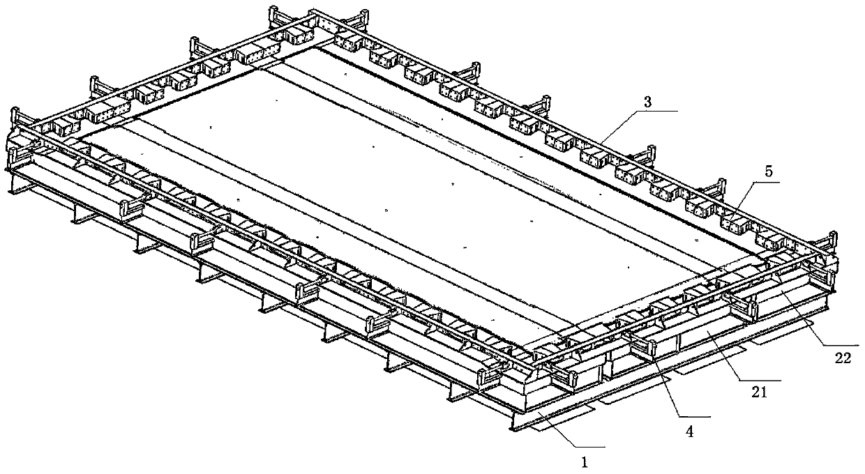
[0030] Embodiment 1: as figure 1 and figure 2 As shown, a high-precision multifunctional concrete bridge deck prefabrication mold according to the present invention includes a base 1, a bottom film 2 positioned on the upper layer of the base 1, a side mold 3 positioned around the bottom film 2, and a demoulding mold positioned outside the side mold. The device 4 and the core film 5 located inside the side mold.

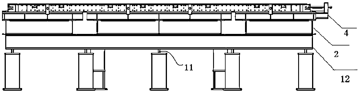
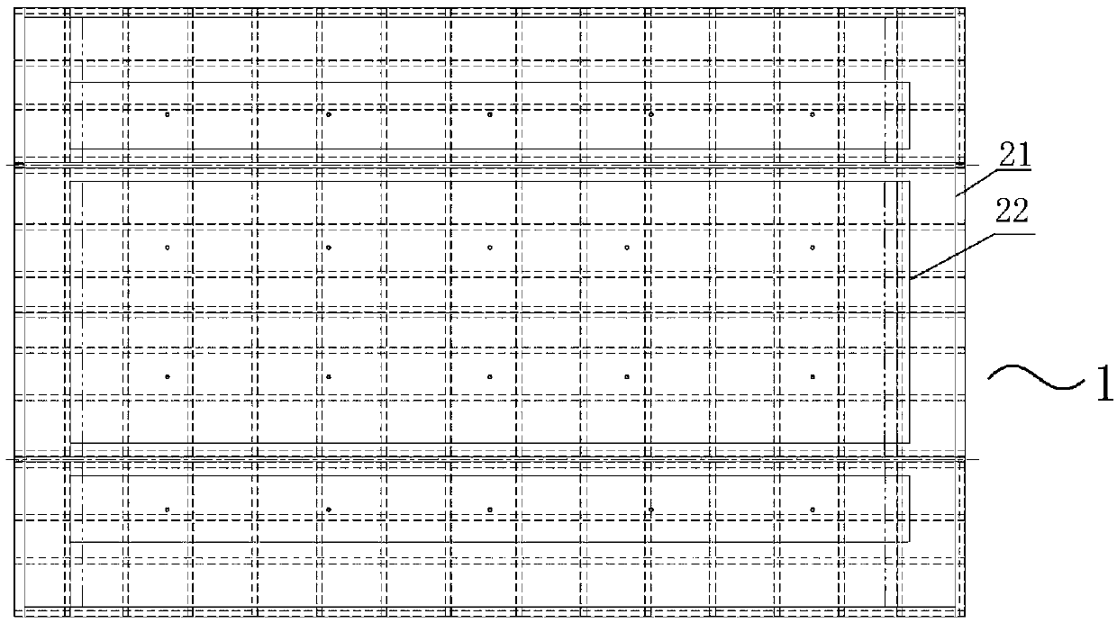
[0031] Such as image 3 and Figure 4 As shown, the base 1 is composed of a number of longitudinal beams parallel to each other and a number of cross beams parallel to each other. The longitudinal beams and the beams are vertically arranged so that the longitudinal beams 11 and the beams 12 are staggered to form a mesh supporting bottom membrane 2; the upper layer of the base 1 is provided with a bottom Die 2, bottom mold 2 is made up of the first bottom mold 21 and the second bottom mold 22 that is positioned at the first bottom mold 21 upper layers, and the firs...

Embodiment 2

[0037] Embodiment 2: based on the structure of embodiment 1, the present invention has made the prefabricated mold of following specification, and concrete preparation method is as follows:

[0038] I-beams and channel steels are used to form a system of beams 12 and longitudinal beams 11, and a foundation pit is set under the base 1 with a height of about 1.2m, which is convenient for screwing bolts. Before the prefabricated mold is assembled, the I-shaped beam of the base 1 is bolted to the embedded plate on the ground, and the overall flatness of the base 1 is adjusted through the bolts.

[0039] In order to facilitate the positioning and assembly of T-shaped embedded components, the connecting part between the base 1 and the bottom mold 2 is divided into three parts, including the middle base and the side bases located on both sides of the middle base, and the base film is also divided into the middle part located above the middle base. The bottom film and the side bottom ...


PUM


Abstract

The invention discloses a high-precision multifunctional concrete bridge deck slab prefabricated mold and a working method thereof. The prefabricated mold comprises a base, a bottom mold positioned onthe upper layer of the base, and side molds which are located on the upper layer of the bottom mold and are distributed along the periphery of the edge of the bottom mold, wherein a plurality of first positioning holes used for positioning reinforcing steel bars are formed in each side mold, a plurality of demolding devices distributed at intervals are arranged on the outer sides of the side molds, a plurality of core molds used for positioning the reinforcing steel bars are arranged on the inner sides of the side molds, and a plurality of lifting devices which penetrate through the base andare used for lifting the bottom mold are arranged at the lower layer of the base. By means of the prefabricated mold, the overall prefabricated precision of a concrete prefabricated bridge deck slab can be guaranteed.

Description

technical field [0001] The invention relates to the field of bridge manufacturing, in particular to a concrete bridge deck prefabrication mold used in the bridge manufacturing field and a working method thereof. Background technique [0002] Steel-concrete composite girders use concrete bridge decks, and factory-like and standardized prefabrication methods are now widely used in construction, which can effectively guarantee the construction quality and speed up the construction progress. It has developed rapidly in my country in recent years. The construction difficulties of prefabricated concrete prefabricated bridge decks mainly include: (1) The pre-embedded steel components must ensure the pre-embedded position accuracy of the pre-embedded steel components in order to achieve accurate matching and alignment with the steel beams under the prefabricated bridge deck; (2) The connecting steel bars at the wet joints between adjacent prefabricated bridge decks are all connected...

Claims


Application Information

Patent Timeline
IPC IPC(8): B28B7/00B28B23/02
CPCB28B7/0002B28B7/0032B28B23/02
Inventor 吴小兵李义成华乐刘志刚王岁利朱新华王亚栋
Owner 中铁宝桥(扬州)有限公司
Why Eureka
Try Eureka