Forming mould for composite radial curved surface back bar of satellite antenna reflector

A composite material and satellite antenna technology, applied in the field of mold design, can solve the problems of the overall weight of the mold, the weight of a single part, the increase of the thickness of the steel mold, and the large curvature of the rib surface, so as to achieve both molding feasibility and manufacturing feasibility. Dependency reduction effect

Active Publication Date: 2019-04-05
SHANGHAI COMPOSITES SCI & TECH CO LTD
View PDF5 Cites 2 Cited by
  • Summary
  • Abstract
  • Description
  • Claims
  • Application Information

AI Technical Summary

Problems solved by technology

[0003] At present, due to the problems that the steel molds on both sides cannot be pressurized in place and the soft molds on both sides have no lay-up reference for composite components with large-sized ribs, the molding method of one steel mold and one side vacuum bag or soft mold pressurization is mostly used. However, for large-scale and complex radial ribs, after using this method, the steel formwork is fixed on the bottom plate between two radial angles as the laying reference, and the adjacent angle area must be realized with a full soft mold structure. The overall pressurization, and so on, three of the six radial angle areas are the all-steel mold laying reference, the three areas are all soft mold pressurization, and the two methods appear at intervals, which will cause two types of product outer contours. The problem with apparent state
On the other hand, the curved surface of the back reinforcement has a large curvature, and the height difference between the highest point and the lowest point is nearly 100mm. If the method of designing the flat bottom plate with the height of the lowest point as the reference plane is adopted, the height of the steel mold in the pressurized soft mold assembly will also be close to 100mm. Generally, the length of commonly used standard screws and pins cannot meet the positioning and fastening of steel moulds. Using large-diameter screws and pins will increase the thickness of the corresponding steel mould, and the overall weight of the mould, and the weight of a single part are both overweight, resulting in difficult operation.

Method used


Image

  • Forming mould for composite radial curved surface back bar of satellite antenna reflector
  • Forming mould for composite radial curved surface back bar of satellite antenna reflector
  • Forming mould for composite radial curved surface back bar of satellite antenna reflector

Examples


Embodiment Construction

[0017] The present invention will be described in detail below in conjunction with specific embodiments. The following examples will help those skilled in the art to further understand the present invention, but do not limit the present invention in any form. It should be noted that those skilled in the art can make several changes and improvements without departing from the concept of the present invention. These all belong to the protection scope of the present invention.

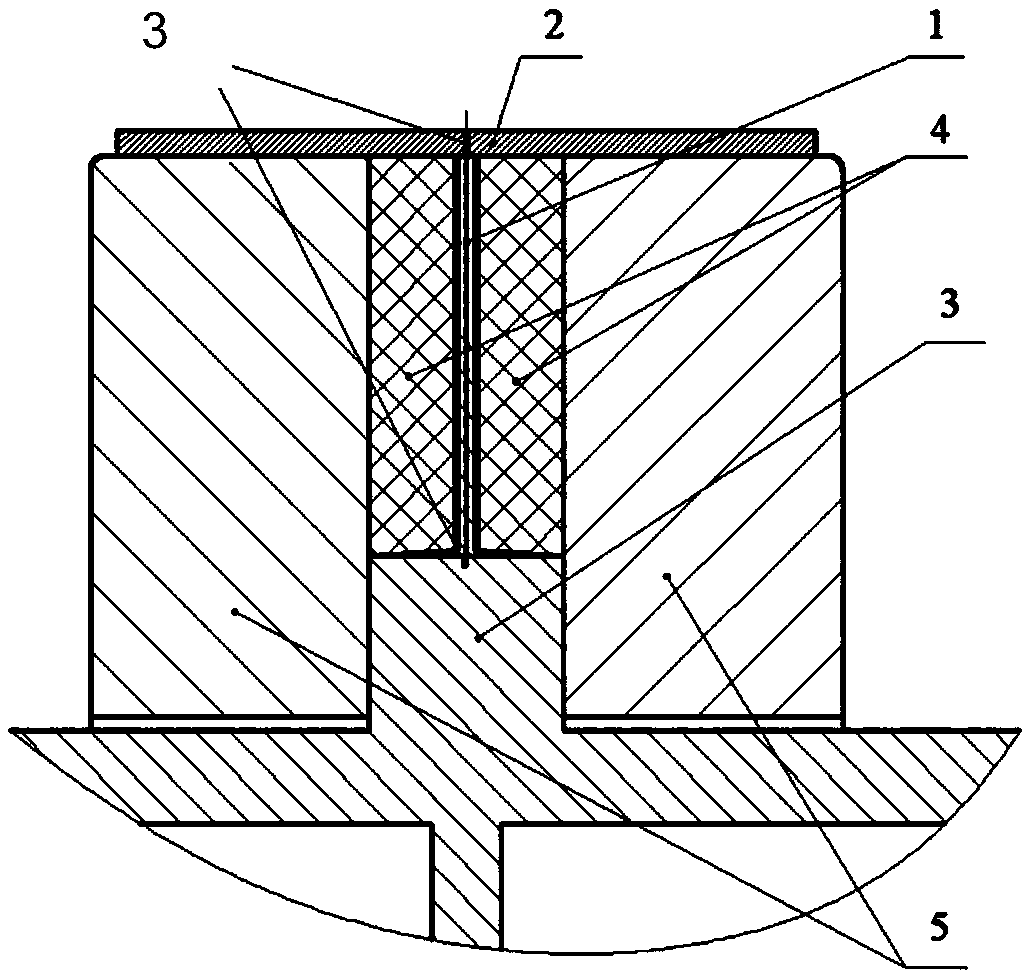
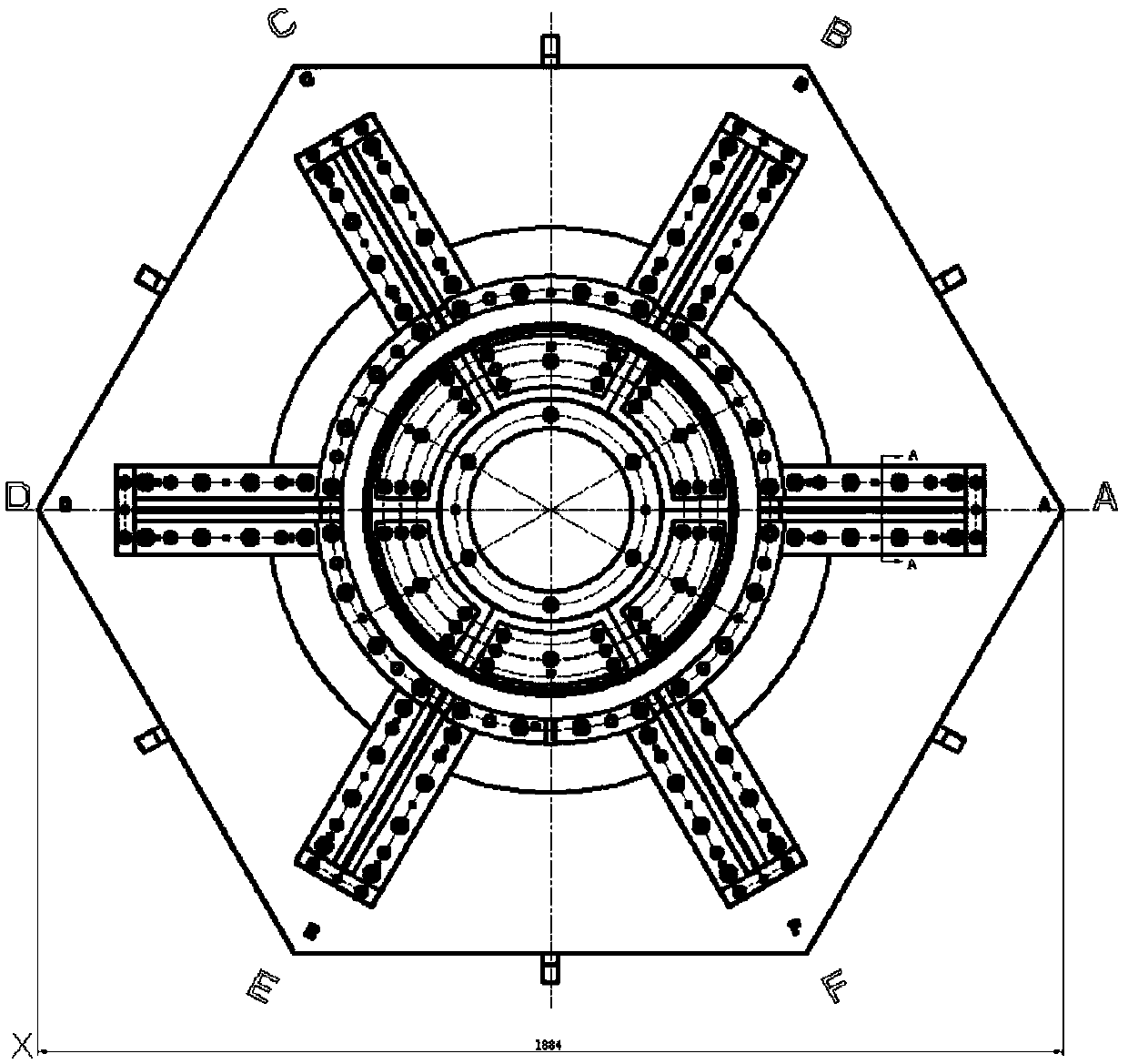
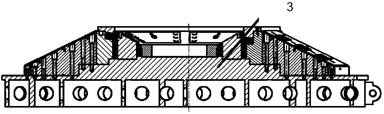
[0018] The invention discloses a design method suitable for forming molds for hexagonal radial curved surface ribs of composite materials for satellite antenna reflectors. On several card slots opened on the surface and the positioning plate of the prefabricated slab, and lay layers on both sides of the prefabricated slab, design the annular steps with increasing height on the bottom plate to position the pressurized soft module components on both sides, and pressurize the soft module modules on both sid...


PUM

PropertyMeasurementUnit
Thicknessaaaaaaaaaa
Widthaaaaaaaaaa

Abstract

The invention provides a forming mould for a composite radial curved surface back bar of a satellite antenna reflector. The overall mould design idea comprises the steps that composite preform plateswith a plurality of positioning convex table structures are adopted, and are positioned on the bottom plate moulding surface and a plurality of clamping grooves formed in preform plate positioning plates; and both sides of the preform plates are overlaid, pressure soft mould assembles on both sides are positioned by designing circular steps with increasing height on a bottom plate, the pressure soft mould assemblies on both sides are composed of steel mould cores and silicone rubber or silicone rubber strips and limiting steel plates of the silicone rubber strips, wherein the pressure soft mould assemblies are coated with the silicone rubber. According to the forming mould for the composite radial curved surface back bar of the satellite antenna reflector, a design method that the composite preform plates are positioned through the clamping grooves formed in the bottom plate and the preform positioning plates, the two sides of the composite preform plates are overlaid and are soft mould pressure is developed.

Description

technical field [0001] The invention relates to mold design, in particular to a molding mold suitable for forming radial curved surface ribs of composite materials for satellite antenna reflectors. In particular, it relates to a design method suitable for forming molds for hexagonal radial curved surface ribs of composite materials for satellite antenna reflectors. Background technique [0002] Due to the use requirements of the satellite reflector, the size of the components is large. In order to ensure sufficient strength, rigidity and high precision requirements, the general components adopt the structure of the skin glued to the back of the large-scale overall reinforcing rib, that is, the back rib described in the present invention. The overall rigidity of the components, and in order to take into account the requirements of lightweight, most of the reinforced back ribs are made of composite material components with high specific strength and specific stiffness. [000...

Claims


Application Information

Patent Timeline
IPC IPC(8): B29C33/00B29C70/54
CPCB29C33/00B29C70/54
Inventor 潘韵叶奇飞叶周军吴文平施静曹恒秀史文锋刘扬郭金海周栋张成祥熊礽智
Owner SHANGHAI COMPOSITES SCI & TECH CO LTD
Why Eureka
Try Eureka