Vehicle driving system

A vehicle drive and vehicle technology, which is applied in the field of rail vehicles, can solve the problems of high operating costs of high-speed rail, and achieve the effects of increasing magnetic driving force, avoiding derailment, and improving stability

Inactive Publication Date: 2019-04-05
CRRC QINGDAO SIFANG CO LTD
View PDF9 Cites 0 Cited by
  • Summary
  • Abstract
  • Description
  • Claims
  • Application Information

AI Technical Summary

Problems solved by technology

[0004] However, due to the high-speed operation of the vehicle, a lot of energy loss will be generated due to the influence of air resistance, which makes the high-speed rail operation cost very high

Method used


Image

  • Vehicle driving system
  • Vehicle driving system
  • Vehicle driving system

Examples


Embodiment 1

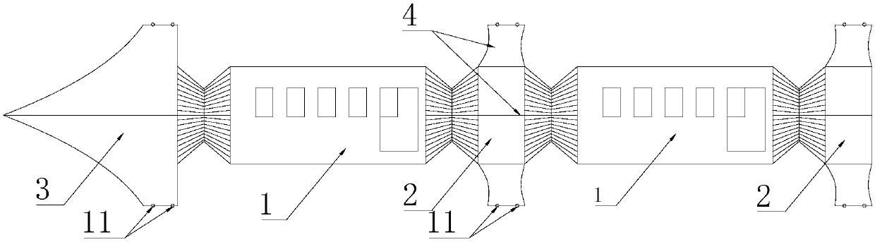
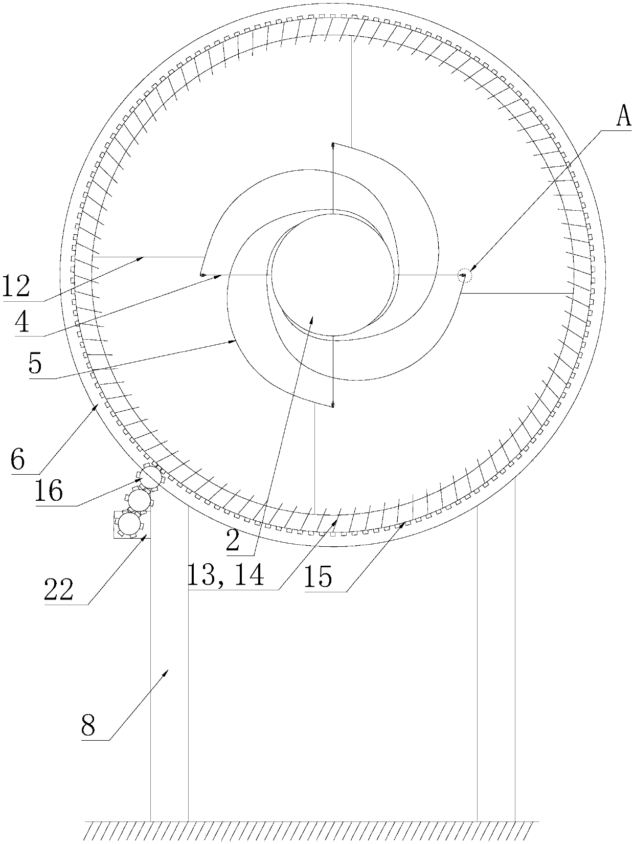
[0044] Such as Figure 1 to Figure 6 As shown, the present embodiment introduces a vehicle drive system. The annular support portion 6 is provided with a coaxial turbine 13 that can relatively rotate around the central axis. The turbine 13 is connected to the output end of the engine 22 through a transmission structure. Engaged, the engine 22 drives the turbine 13 to rotate to generate jet airflow along the centerline direction of the annular support part 6, and the jet airflow pushes the vehicle to move forward.

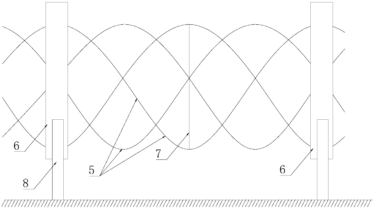
[0045] In this embodiment, the vehicle is provided with a rotating part 2 that can rotate around the moving direction. The outer circumference of the rotating part 2 is provided with wheels 11. The wheels 11 are correspondingly installed into the guide rail 5 extending along the cylindrical helix, so that the rotating part 2 is supported by the guide rail 5. The rotating part 2 is pushed forward by the jet airflow generated by the turbine 13 during the rotation arou...

Embodiment 2

[0050] Such as figure 1 , figure 2 , Figure 4 to Figure 7 As shown, the present embodiment introduces a vehicle drive system. A coil 23 coaxially arranged in the ring-shaped support part 6 is connected to the power supply device, and the power supply device feeds a current to the coil 23 to generate a magnetic field. The vehicle passing through the annular support part 6 is pushed forward by the magnetic driving force generated by the magnetic field.

[0051] In this embodiment, the vehicle is provided with a rotating part 2 that can rotate around the moving direction. The outer circumference of the rotating part 2 is provided with wheels 11. The wheels 11 are correspondingly installed into the guide rail 5 extending along the cylindrical helix, so that the rotating part 2 is supported by the guide rail 5. The rotating part 2 continuously cuts the magnetic field to generate a magnetic driving force during the rotation process, so that the rotating part 2 is affected by the...

Embodiment 3

[0056] This embodiment is based on the above-mentioned embodiment one or two, and also has the following technical features:

[0057] In this embodiment, a starting power system is provided on the vehicle, and the starting power mechanism includes a storage battery and an electric motor arranged on the vehicle. The storage battery supplies power to the motor to drive the output end of the motor to rotate, and the output end of the motor is connected to the wheels 11 through a transmission system to drive Wheels 11 rotate to propel the vehicle forward.


PUM


Abstract

The invention discloses a vehicle driving system. The vehicle driving system comprises multiple circular ring-shaped supporting parts alternately arranged in a vehicle running direction; and driving devices arranged on the circular ring-shaped supporting parts provide driving forces to a vehicle passing through the interiors of the circular ring-shaped supporting parts so as to drive the vehicle to move forwards along a track. By arranging the track in the circular ring-shaped supporting parts, the driving acting force is provided for the vehicle passing through the supporting parts by using the driving devices arranged on the circular ring-shaped supporting parts so that the vehicle runs at a high speed under the effect of the driving force.

Description

technical field [0001] The invention belongs to the field of rail vehicles, and in particular relates to a vehicle drive system; in particular, it relates to a drive system for a vehicle structure running along a helical track. Background technique [0002] High-speed railway is a railway system designed for high-speed railways and allowing trains to run at high speeds. The world's first official high-speed railway system is the Japanese Shinkansen, which was completed and opened to traffic in 1964. The design speed is 200km / h, so the initial speed standard of high-speed railway is 200km / h. Later, with the advancement of technology, the speed of trains became faster. Different countries in different eras had different definitions of high-speed railways, and stipulated their own detailed technical standards for high-speed railway levels according to their own conditions. all the same. [0003] Traditional high-speed railways generally use ballastless tracks, and a small num...

Claims


Application Information

Patent Timeline
Patent Type & Authority Applications(China)
IPC IPC(8): B61C11/00B61C11/06
Inventor 张蕾林蓝董青婧张琪
Owner CRRC QINGDAO SIFANG CO LTD
Why Eureka
Try Eureka