Magneto-rheological elevator buffer and control method
A buffer and magneto-rheological technology, applied in the direction of shock absorbers, shock absorbers, spring/shock absorbers, etc., can solve poor adaptability, inability to actively adjust the damping force of the buffer, spring buffer and hydraulic buffer damping The force cannot be adjusted in real time to achieve the effect of improving performance, improving comfort and stability, and good adaptability
- Summary
- Abstract
- Description
- Claims
- Application Information
AI Technical Summary
Problems solved by technology
Method used
Image

Examples
Embodiment 1
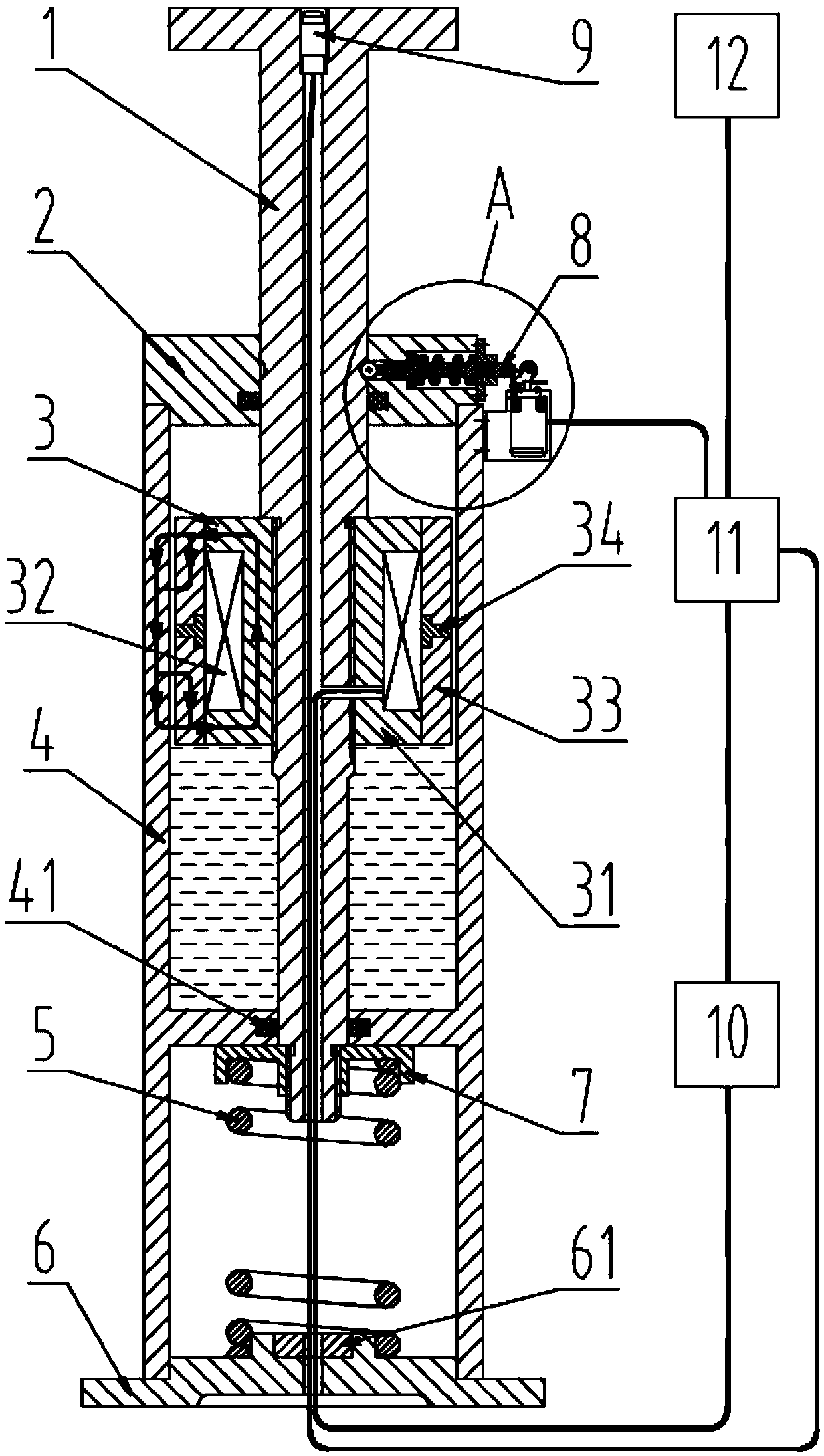
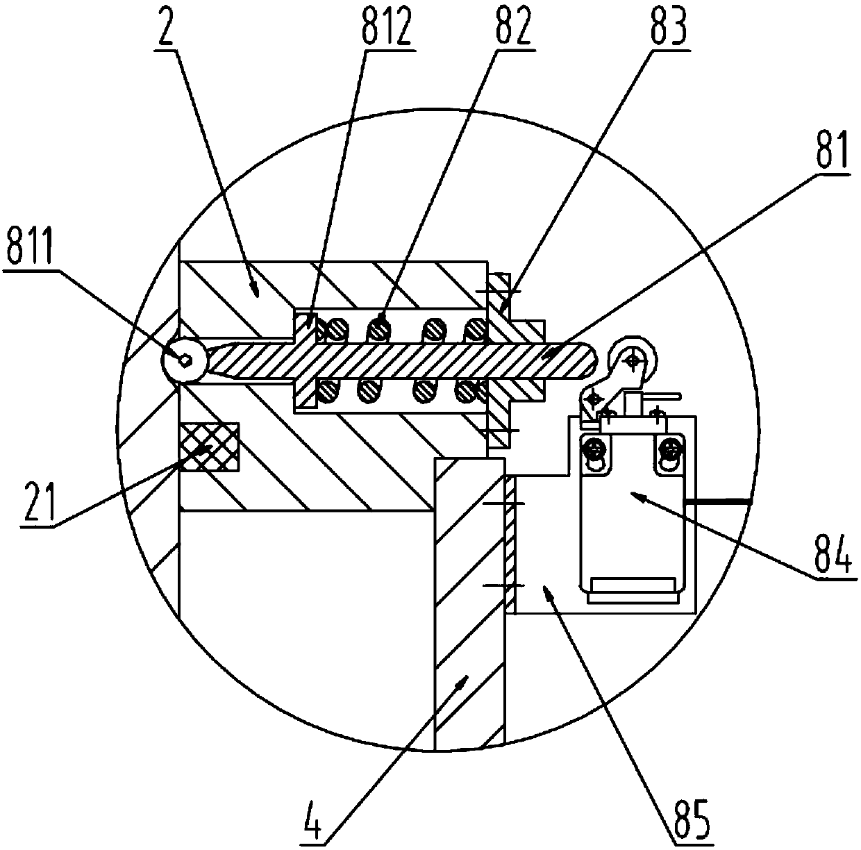
[0035] like figure 1As shown, this embodiment discloses a magneto-rheological elevator buffer, including a cylinder 4, an upper end cover 2 located at the top of the cylinder 4 and a lower end cover 6 located at the bottom of the cylinder 4, and a cavity inside the cylinder 4. The piston rod 1, the piston assembly 3, the compression spring 5, the switch assembly 8 located inside the upper end cover 2, the power supply unit 10, the controller 11 and the sensor 12. The upper part of the cylinder body 4 and the upper end cover 2 form an upper cavity, and the piston assembly 3 is arranged inside, and the magnetorheological fluid is filled in the cavity of the upper cavity; the lower part of the cylinder body 4 and the lower end cover 6 form a lower cavity, and a compression spring 5 is arranged inside . The piston rod 1 is divided into four stages of stepped shafts from top to bottom. The first stage of the stepped shaft is coaxially sealed and slidably connected with the upper e...
Embodiment 2
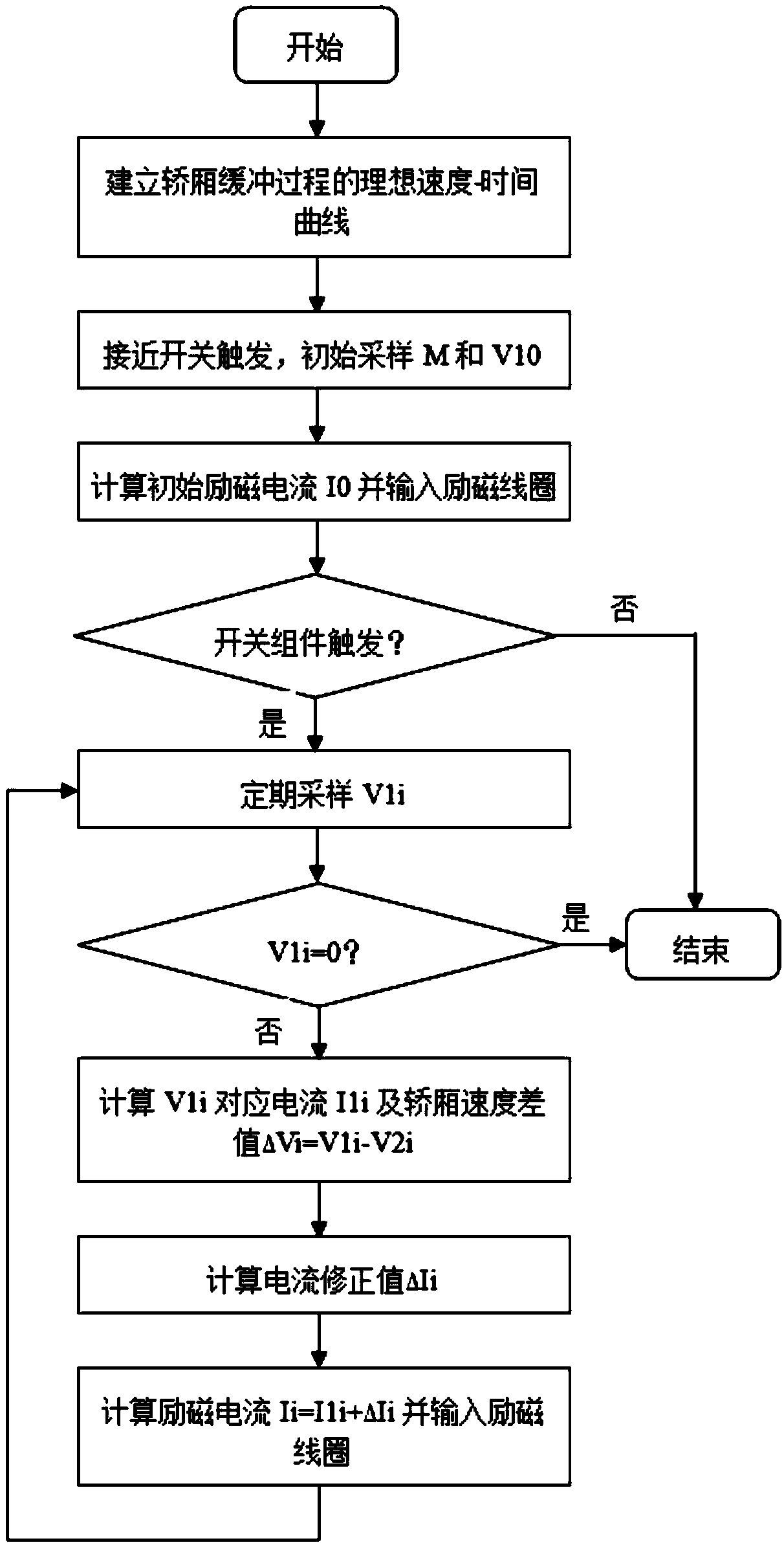
[0048] like image 3 As shown, this embodiment discloses a method for controlling a magneto-rheological elevator buffer, including the following steps:
[0049] S1, establish the ideal speed-time curve of the working process of the buffer, and store the ideal speed-time curve into the storage module of the controller 11;
[0050] S2. When the proximity switch 9 detects that the elevator car is about to hit the buffer, it is triggered, and the signal is sent to the controller 11, and the controller 11 sends a control command to the sensor 12. At this time, the sensor 12 samples the car quality M and the car speed V 10 and fed back to the controller 11 to calculate the initial excitation current I 0 And the excitation coil 32 is input by the power supply device 10;
[0051] S3. During the buffering process of the car, the sensor 12 samples the car speed V every interval ΔT 1i , calculate the corresponding car speed V 1i The excitation current I 1i , and the difference ΔV be...
PUM
 Abstract
Description
Claims
Application Information
 - R&D Engineer
- R&D Manager
- IP Professional
- Industry Leading Data Capabilities
- Powerful AI technology
- Patent DNA Extraction
Browse by: Latest US Patents, China's latest patents, Technical Efficacy Thesaurus, Application Domain, Technology Topic.
© 2024 PatSnap. All rights reserved.Legal|Privacy policy|Modern Slavery Act Transparency Statement|Sitemap