Integrally-formed drainage ditch and construction method thereof

A technology of integral molding and drainage ditch, which is applied in the direction of waterway system, water supply device, sewer pipeline system, etc. It can solve the problems of cumbersome construction drainage ditch appearance and main body quality, increased difficulty of construction, and more manpower, so as to improve the molding rate of one pouring , Reduce the excavation process and manpower, and reduce the effect of project cost

Active Publication Date: 2019-04-05
HANGZHOU JIANGRUN TECH LIMITED
View PDF6 Cites 11 Cited by
  • Summary
  • Abstract
  • Description
  • Claims
  • Application Information

AI Technical Summary

Problems solved by technology

[0004] In order to facilitate the construction and ensure the quality of the drainage ditch, the drainage ditch is required to be set on a relatively dense soil layer. However, in most parts of southern my country, the surface water level is relatively shallow, which undoubtedly increases the difficulty of construction. Traditional construction requires a large number of formwork to ensure the completion of construction. , and require more manpower
[0005] In view of the geological defects, cumbersome construction, drainage ditch appearance and main quality problems encountered in the above drainage ditch construction, it is necessary to invent a simple and effective integrally formed drainage ditch construction method to simplify the construction process, reduce the construction cost, and ensure construction. Under the premise of quality, at the same time, it can save resources

Method used


Image

  • Integrally-formed drainage ditch and construction method thereof
  • Integrally-formed drainage ditch and construction method thereof
  • Integrally-formed drainage ditch and construction method thereof

Examples


Embodiment

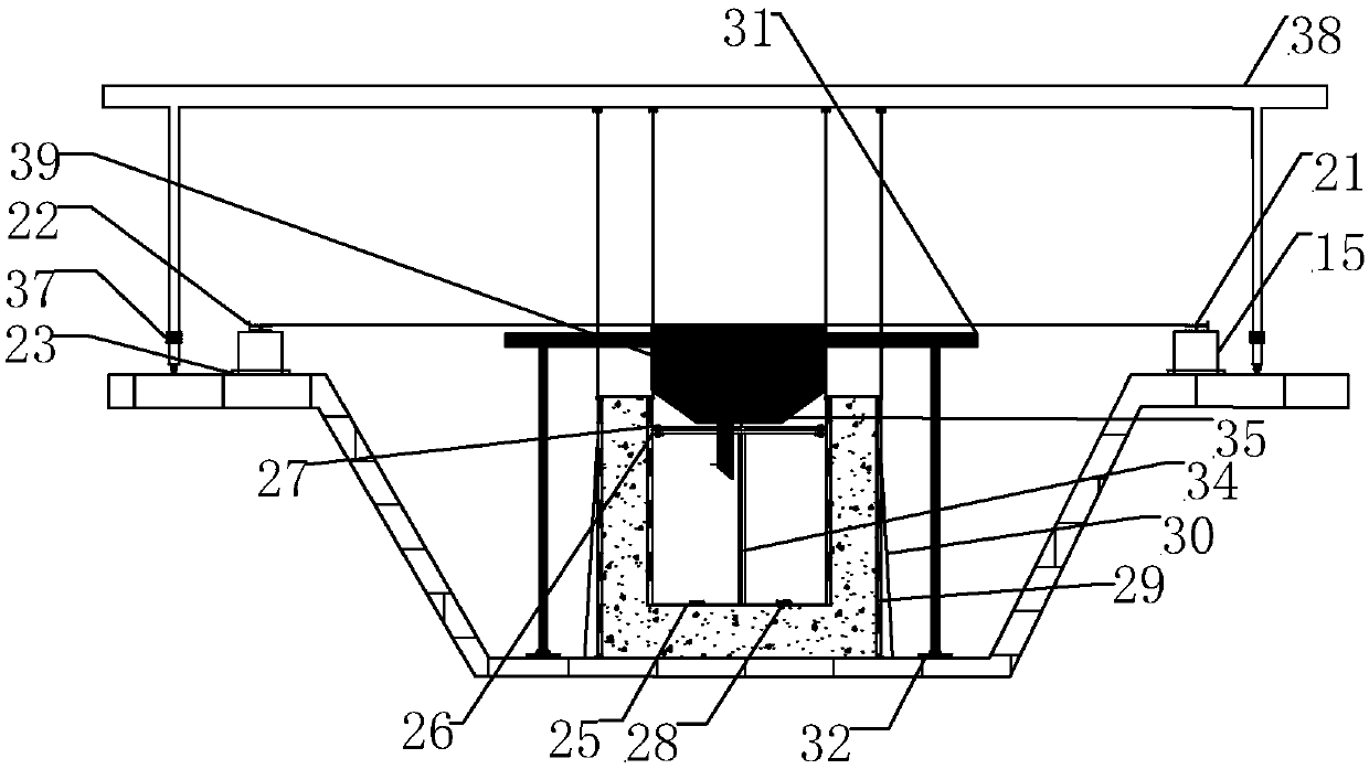
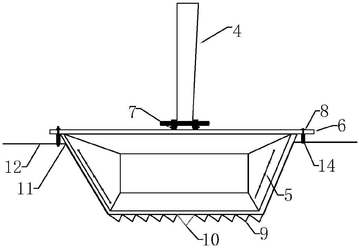
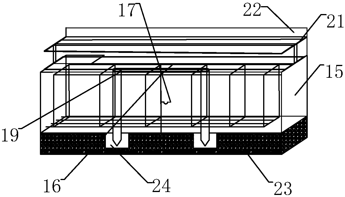
[0050] Example: such as Figure 1 to Figure 8 As shown, the integrated drainage ditch includes the drainage ditch body, and also includes a shaped bucket 5, a shaped slope scraper 11, a sliding form track 21, a shaped side form 29, and a bottom scraping beam frame 25, and a sliding form track 21 Assembled on both sides of the above-mentioned drainage ditch body, it can be used to move other excavating devices installed on the sliding form track 21. The above-mentioned stereotyped side mold 29 is arranged in the drainage ditch body for positioning the side of the drainage ditch body, and the side of the drainage ditch While shaping, the above-mentioned bottom scraping beam frame 25 is movably arranged at the bottom of the above-mentioned drain body, so that the bottom of the drain body remains flat, and the shaped side mold 29 can be fixedly installed on the above-mentioned bottom scraping beam frame 25, The above-mentioned bottom scraping beam frame 25 is connected to the slid...


PUM


Abstract

The invention discloses an integrally-formed drainage ditch, which comprises a drainage ditch body, a shaped digging bucket, a shaped slope scraper, sliding mold rails, a shaped side mold and a bottomscraping cross beam frame, wherein the sliding mold rails are assembled on two sides of the drainage ditch body; the shaped side mold is arranged in the drainage ditch body; the bottom scraping crossbeam frame is arranged at the bottom of the drainage ditch body; the shaped side mold can be fixedly arranged on the bottom scraping cross beam frame; the bottom scraping cross beam frame is connected with a sliding cross beam gantry and is dragged and slid by the sliding cross beam gantry; and the shaped side mold is connected with a side mold gantry and is dragged and slid by the side mold gantry. The drainage ditch simplifies the construction steps, saves the construction time, reduces the construction cost, is easy to excavate and form, has low operation difficulty, so that the safety inthe construction process can be effectively ensured; and the drainage ditch has beautiful appearance and good quality. The second object of the invention is the construction method of the integrally-formed drainage ditch, the method is applied to the integrally-formed drainage ditch, and further has the advantages of high safety, high convenience and the like.

Description

technical field [0001] The invention relates to technical fields such as municipal roads and bridges, in particular to an integrally formed drainage ditch and a construction method thereof. Background technique [0002] Urban drainage system is an engineering facility system for treating and removing urban sewage and rainwater. It is an integral part of urban public facilities. Urban drainage system planning is an integral part of urban overall planning. Urban drainage systems are usually composed of drainage pipes and sewage treatment plants. In the case of sewage and rainwater diversion system, sewage is collected by drainage pipes, sent to sewage treatment, discharged into water bodies or recycled; rainwater runoff is collected by drainage pipes, and discharged into nearby water bodies. [0003] The urban drainage system is very critical in the daily operation of the city and when it encounters heavy precipitation. At present, with the construction of urbanization and the...

Claims


Application Information

Patent Timeline
Patent Type & Authority Applications(China)
IPC IPC(8): E03F3/04E03F3/06
CPCE03F3/046E03F3/06
Inventor 王新泉
Owner HANGZHOU JIANGRUN TECH LIMITED
Why Eureka
Try Eureka