Heater built-in valve

A technology for heaters and valve stems, which is applied to valve heating/cooling devices, valve lifts, valve details, etc. It can solve problems such as uneven temperature, achieve easy operation, easy replacement, and reduce the difficulty of plugging and unplugging

Inactive Publication Date: 2019-04-05
FUJIKIN INC
View PDF6 Cites 0 Cited by
  • Summary
  • Abstract
  • Description
  • Claims
  • Application Information

AI Technical Summary

Problems solved by technology

A valve with a built-in heater is used to solve such problems. However, in the case of a valve with a built-in heater in the valve element disclosed in Patent Document 1, liquefaction of gas may occur depending on conditions due to temperature unevenness inside the valve, The case of evaporation

Method used


Image

  • Heater built-in valve
  • Heater built-in valve
  • Heater built-in valve

Examples


Embodiment Construction

[0036] Preferred embodiments of the present invention will be described in detail below by way of example with reference to the accompanying drawings. However, the relative arrangement and the like of the components described in the present embodiment are merely illustrative examples unless otherwise specified, and do not limit the scope of the present invention thereto. In addition, for the sake of convenience, the directions of members and the like may be referred to as up, down, left, and right based on the directions on the drawings, but these directions do not limit the scope of the present invention.

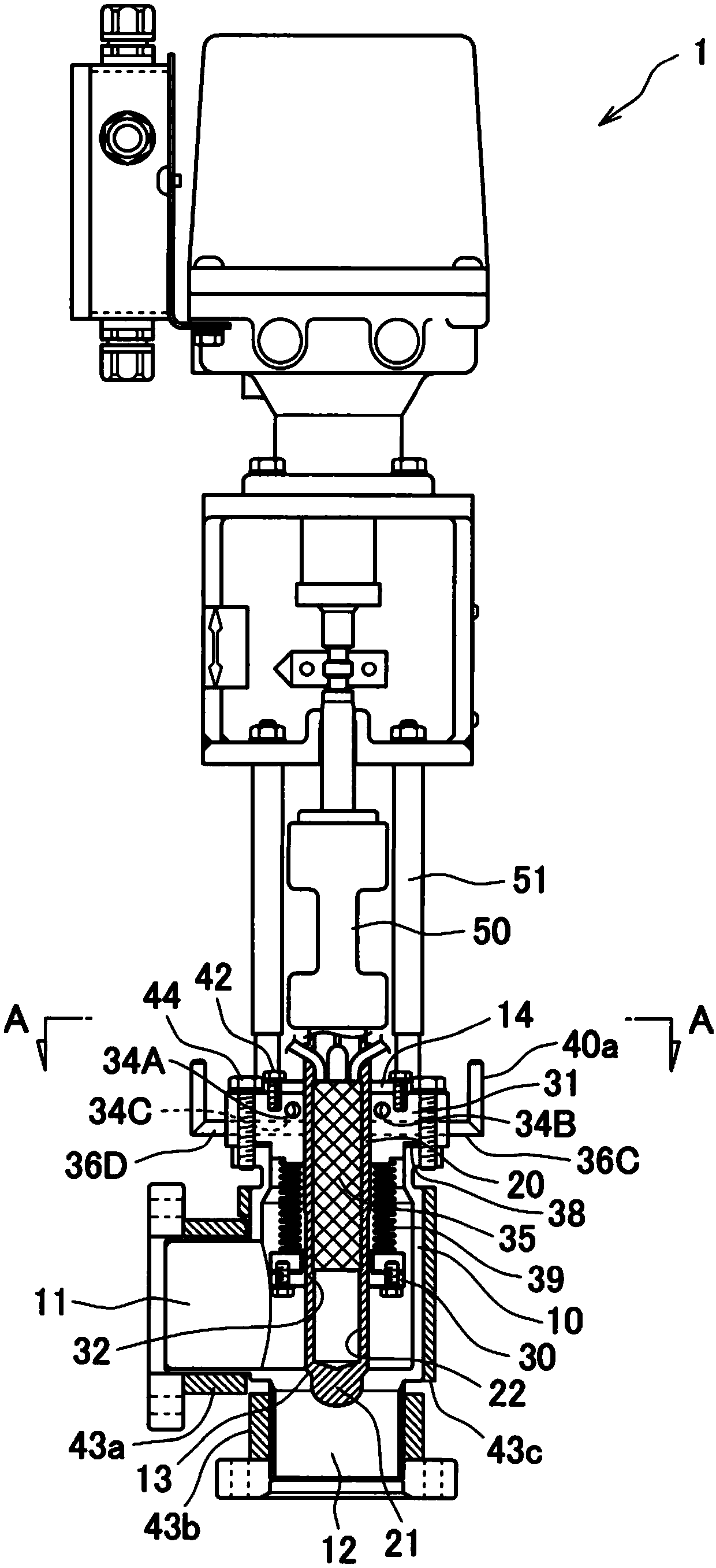
[0037] figure 1 It is a figure which shows Example 1 of the heater built-in valve of this invention, This valve 1 is also called a heater built-in vacuum on-off valve.

[0038] The valve body 10 is provided with an inlet channel 11 and an outlet channel 12 , and a valve seat 13 is formed therebetween. The fluid flows in from the left and flows downward with the valve ope...


PUM


Abstract

The invention provides a valve with a built-in heater capable of reducing the liquefaction and evaporation of gas passing through a valve as compared with a conventional valve with built-in heater. Aheater built-in valve (1) is provided with a valve body (10) having a gas inlet passage (11), a gas outlet passage (12), and a valve seat (13) formed between the passages; a valve stem (20) having a valve body (21) that abuts against/separates from the valve seat (13) at the lower end thereof; a cover member (31) that is fixed in an airtight manner to the upper part of the valve body (10) and through which the valve stem (20) passes; and a bellows (39) welded and fixed to the valve stem (20) and the lid member (31), the lid member (31) having at least one heater insertion hole (34) into whichat least one rod-shaped heater (36) is inserted.

Description

technical field [0001] The present invention relates to a heater built-in valve. Background technique [0002] The valve installed in the middle of the flow path connecting the vacuum chamber to the vacuum pump in the semiconductor manufacturing process includes a device with a built-in heater and is used under high temperature conditions exceeding 200°C. [0003] The valve described in Patent Document 1 is a bellows valve for high temperature, is heated from the outside, and has a heater built into the valve body. [0004] prior art literature [0005] patent documents [0006] Patent Document 1: Japanese Patent No. 4923105 Contents of the invention [0007] When the valve is used under high temperature conditions, depending on the type of gas flowing through the valve, liquefaction and evaporation of the gas may occur inside the valve due to uneven temperature. A valve with a built-in heater is used to solve such problems. However, in the case of a valve with a built...

Claims


Application Information

Patent Timeline
Patent Type & Authority Applications(China)
IPC IPC(8): F16K1/36F16K49/00
CPCF16K1/36F16K49/00
Inventor 平松浩司曾我尾昌彦药师神忠幸
Owner FUJIKIN INC
Why Eureka
Try Eureka