
Heat exchange two-layer pipe sealing structure and installing fixture and method thereof

A technology of sealing structure and installation fixture, which is applied in the direction of sealing surface connection, pipe/pipe joint/pipe fitting, passing components, etc., which can solve the problems of large impact on the fatigue life of the sealing ring, large volume of the sealing structure, and pollution of two media, etc. Achieve the effect of stable and durable sealing effect, good sealing effect and small deformation

Pending Publication Date: 2019-04-05
广州市科绿士环保设备有限公司
View PDF11 Cites 1 Cited by
  • Summary
  • Abstract
  • Description
  • Claims
  • Application Information

AI Technical Summary

Problems solved by technology

In this sealing method, the contact surface between the sealing ring, the outer tube and the steps is sharp, resulting in stress concentration, which has a great impact on the fatigue life of the sealing ring and needs to be replaced frequently
[0004] Moreover, the existing sealing structure is bulky, and the nut is exposed after installation, which is unsightly. Once the seal is not tight due to wrong screwing, it will cause cross-contamination of the two media

Method used


Image

  • Heat exchange two-layer pipe sealing structure and installing fixture and method thereof
  • Heat exchange two-layer pipe sealing structure and installing fixture and method thereof
  • Heat exchange two-layer pipe sealing structure and installing fixture and method thereof

Examples


Embodiment Construction

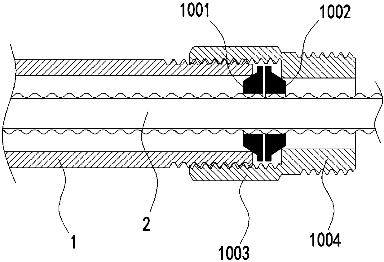
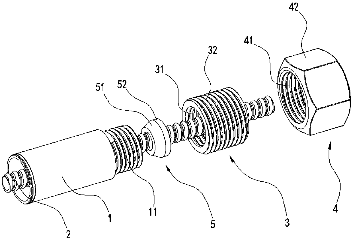
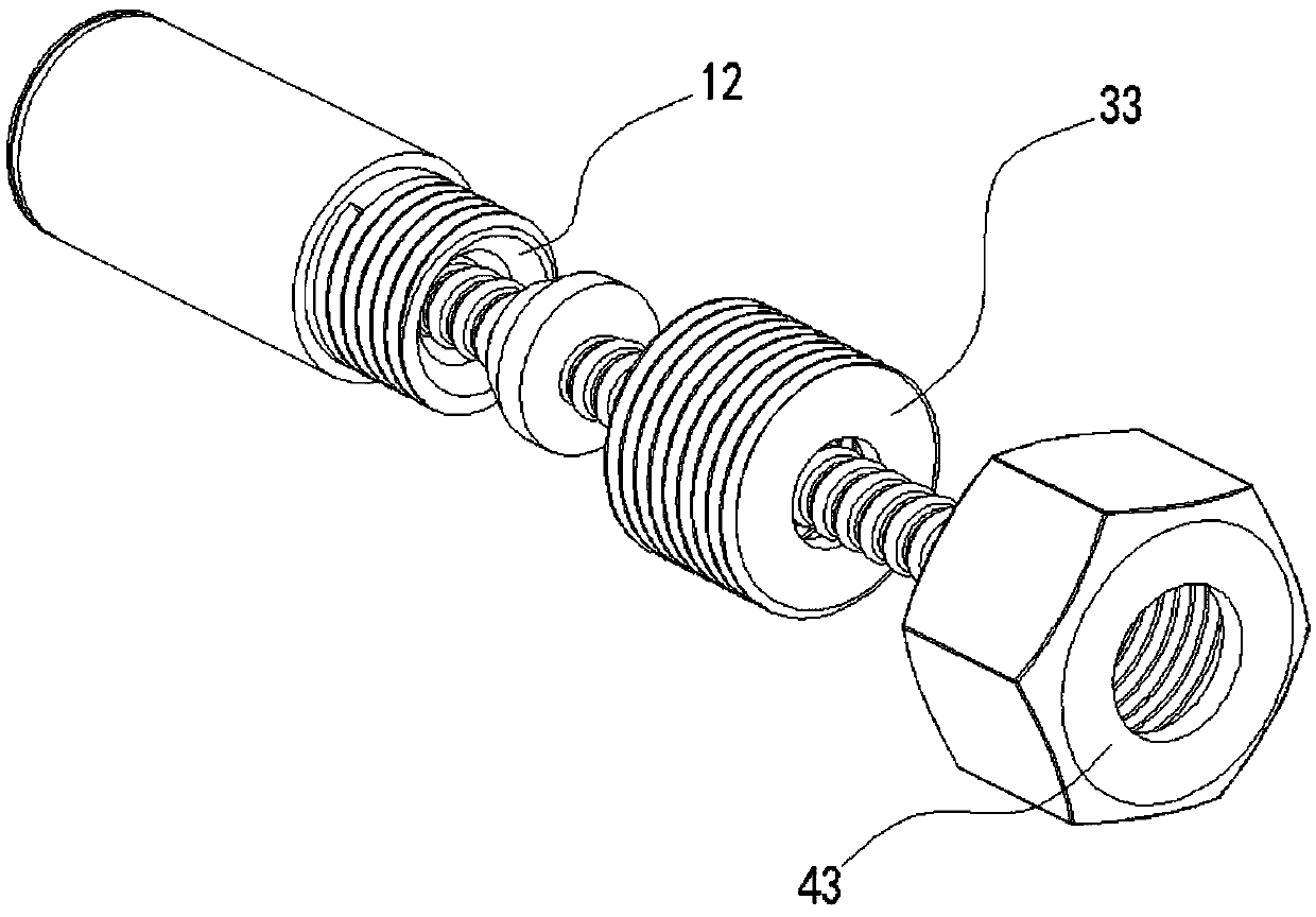
[0027] In order to make the purpose of the present invention, technical solutions and advantages clearer, the following will combine figure 2 - Figure 9 The accompanying drawings describe the present invention in further detail.

[0028] refer to figure 2 - Figure 5 As shown, a heat exchange double-layer tube sealing structure includes an outer tube 1, an inner tube 2 arranged inside the outer tube 1, and a sealing member 5, and the sealing member 5 is sleeved on the inner tube 2; the sealing member 5 includes an outer slope 51 and Cylinder 52, the cylinder 52 is affixed to the larger end of the outer slope 51, the diameter of the cylinder 52 is the same as the diameter of the larger end of the outer slope 51;

[0029] The end 11 of the outer tube 1 has an inner bevel 12, and the end of the inner bevel 12 with a larger diameter faces the opening of the end 11 of the outer tube 1, and the outer bevel 51 matches the inner bevel 12;

[0030] The outer wall of the outer in...


PUM


Abstract

The invention discloses a heat exchange two-layer pipe sealing structure. The heat exchange two-layer pipe sealing structure comprises an outer pipe, an inner pipe arranged in the outer pipe and a sealing component; the sealing component is installed on the inner pipe in a sleeving mode and comprises an external bevel; and the end of the outer pipe is provided with an internal bevel, and the external bevel and the internal bevel closely abut against each other. The invention further discloses an installing fixture. The installing fixture comprises an installing barrel, the inner side wall of the installing barrel is in threaded fit with the outer side wall of the connecting barrel, and an opening of the end of the installing barrel is provided with a stop body used for stopping the connecting barrel. The invention further discloses an installing method. The installing barrel is twisted to be installed on the connecting barrel through a thread in a sleeving mode, axial motion of the connecting barrel is stopped through the stop body, thus, the connecting barrel rotates along with the installing barrel, the installing barrel continues being twisted to be installed at the end of the outer pipe through a thread in a sleeving mode, the sealing component is pressed through a pressing body, the external bevel is made to be tightly attached to the internal bevel, the connecting barrelis welded to or adheres to the end of the outer pipe through welding or bonding equipment, and the installing barrel is reversely twisted to be separated from the connecting barrel. The heat exchangetwo-layer pipe sealing structure is better and more durable in sealing.

Description

technical field [0001] The invention relates to the field of pipe sealing connection, in particular to a heat exchange double-layer pipe sealing structure, an installation fixture and an installation method thereof. Background technique [0002] The heat exchange double-layer tube includes an outer tube and an inner tube arranged inside the outer tube. Inside the inner tube is a first medium channel, and between the outer wall of the inner tube and the inner wall of the outer tube is a second medium channel. When the first and second medium channels are respectively When media with different temperatures are circulated, heat exchange will take place between the two media. This kind of heat exchange double-layer tube is widely used in various civil and industrial heat exchange equipment such as water dispensers and evaporative concentrators. It is used for The core component of heat exchange. [0003] At the end of the heat exchange double-layer tube, it is necessary to seal...

Claims


Application Information

Patent Timeline
Patent Type & Authority Applications(China)
IPC IPC(8): F16L19/028F16L19/03
CPCF16L19/0212F16L19/028
Inventor 吴成英方乐斌洪腾忠
Owner 广州市科绿士环保设备有限公司
Learn More