
Spiral robot capable of moving on curved surface in cavity

A technology of helical robot and inner surface, applied in the field of robots, can solve problems such as jamming, the robot cannot work normally in the pipeline, and the pipeline robot cannot move forward, and achieves the effect of wide application range and smooth fluctuation.

Pending Publication Date: 2019-04-05
SOUTHWEST UNIVERSITY
View PDF0 Cites 1 Cited by
  • Summary
  • Abstract
  • Description
  • Claims
  • Application Information

AI Technical Summary

Problems solved by technology

Due to various obstacles in the pipeline, the pipeline robot will not be able to move forward or get stuck during the exploration process, making the robot unable to work normally in pipeline construction, inspection, maintenance and other operations

Method used


Image

  • Spiral robot capable of moving on curved surface in cavity
  • Spiral robot capable of moving on curved surface in cavity
  • Spiral robot capable of moving on curved surface in cavity

Examples


Embodiment 1

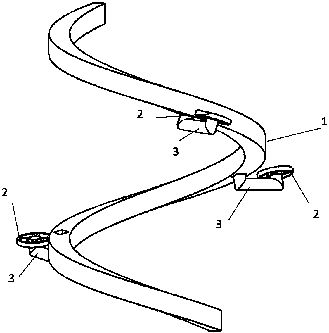
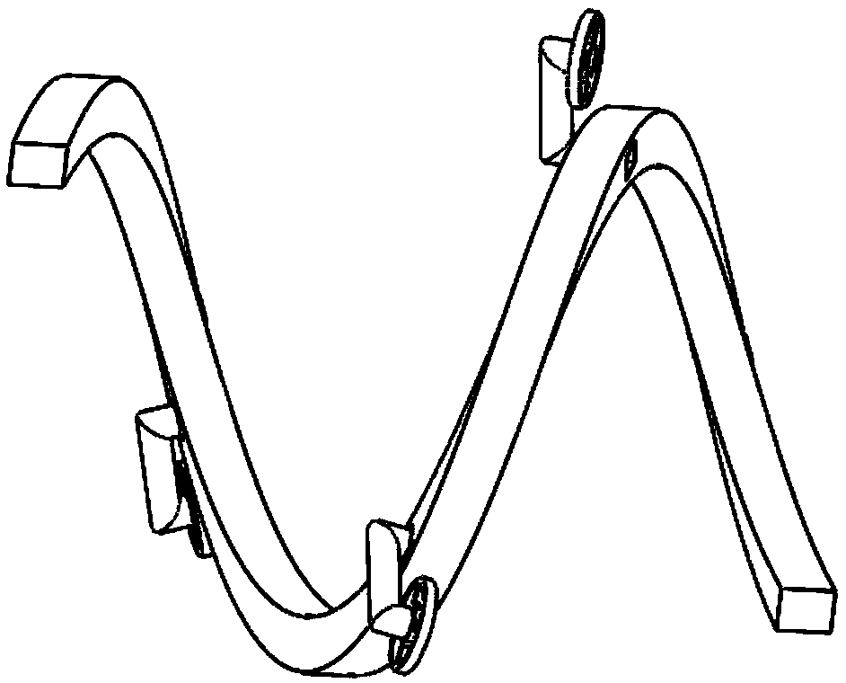
[0041] This example is a three-wheeled spiral robot, the structure of the robot is as follows: Figure 10shown. The structure is composed of a spiral body 1, three action wheels 2, elastic devices and other structures. The length of the spiral body 1 of the robot is between 1 and 2 turns, and 1.5 turns is a moderate length. The appropriate pitch and thickness of the body 1 can ensure that the gap can pass through obstacles; the three action wheels 2 are evenly placed on the body 1, an action wheel 2 is installed every 120 degrees in the direction of the pipe section plane; the installation direction of the action wheel 2 is along the helix direction where the spiral body 1 is located, and each action wheel 2 is driven by a motor. The action wheel 2 is connected with the body 1 through an elastic device. The action wheel 2 has a certain suspension device. The compression direction of the suspension device is from the axial center of the pipeline to the inner wall of the pipeli...

Embodiment 2

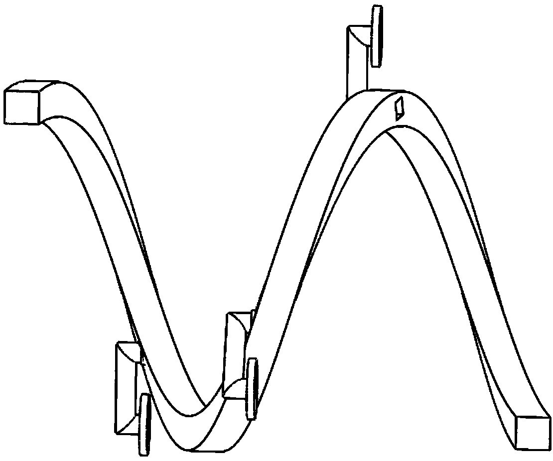
[0044] This example is a six-wheel spiral robot, the structure of the robot is as follows Figure 11 shown. The structure is composed of a spiral body 1, six action wheels 2, connecting devices 3 and other structures. The length of the spiral body 1 of this robot is between 1 and 2 turns, and 1.5 turns is a moderate length, and suitable pitch and body 1 thickness can allow this gap to ensure passing through obstacles. The six action wheels 2 are divided into two groups AB. When the motor drives the action wheels 21 of group A to move, the robot can move forward and backward in the pipeline. The action wheels 22 of group B are installed flat. When the motor drives the action wheels 22 of group B When moving, the robot can rotate in place in the pipeline, and at this time, the robot only rotates but does not move forward or backward. The body 1 of the robot itself is elastic. In a relaxed state, the diameter is slightly about the inner diameter of the pipe. After being compres...


PUM


Abstract

The invention belongs to the field of robots, and relates to a spiral robot capable of moving on a curved surface in a cavity. The robot is composed of a spiral vehicle body and a plurality of travelling wheels arranged on the vehicle body through a connecting device, wherein the travelling wheels are used for driving the vehicle body to spirally move forwards and / or to in-situ horizontally rotatein the cavity. According to the robot, the defects that an existing obstacle crossing robot cannot do spiral curved surface movement in a narrow pipeline and cannot cross an obstacle are overcome, the spiral robot capable of moving on the curved surface in the cavity is provided, so that the robot can normally move when encountering the obstacle in a narrow space, and the robot is stable and small in fluctuation. The machine body of the robot is the spiral vehicle body, the special machine body shape ensures that the robot can smoothly cross the obstacle, and ensures that the robot can do spiral movement when the robot encounters the obstacle in the pipeline. The robot is wide in application range and can be used in moving equipment which needs to travel in the narrow space with the obstacles such as a mobile robot, and an obstacle crossing vehicle.

Description

technical field [0001] The invention belongs to the field of robots, and relates to a screw robot that moves on a curved surface in a cavity. Background technique [0002] With the development of science and technology, there are more and more pipeline infrastructure in life, and the development of pipeline robots is also faster. Due to the existence of various obstacles in the pipeline, the pipeline robot will not be able to advance or get stuck during the walking exploration process, making the robot unable to work normally in pipeline construction, inspection, maintenance and other operations. Contents of the invention [0003] Therefore, in order to solve the problems of narrow space in the pipeline, curved surfaces around the cavity of the pipeline, and obstacles inside the pipeline, the present invention proposes a screw robot that moves on the curved surface in the cavity. When the robot encounters an obstacle in the narrow cavity, the robot can pass the obstacle a...

Claims


Application Information

Patent Timeline
IPC IPC(8): F16L55/32F16L101/30
CPCF16L55/32F16L2101/30
Inventor 王宇俊方灿王强王文平
Owner SOUTHWEST UNIVERSITY
Learn More