Strength steel pipe plane center positioning device and application method thereof

A center positioning and center position technology, which is applied in the direction of measuring devices, mechanical devices, workpiece clamping devices, etc., can solve the problems of low precision, inconvenient positioning, and low efficiency, and achieve high precision, convenient positioning, and reliable connection.

Pending Publication Date: 2019-04-05
CHINA CONSTR SENVENTH ENG BUREAU INSTALLATION ENG
View PDF0 Cites 1 Cited by
  • Summary
  • Abstract
  • Description
  • Claims
  • Application Information

AI Technical Summary

Problems solved by technology

[0003] In view of the deficiencies in the above-mentioned background technology, the present invention proposes a stiff-type steel pipe plane center positioning device and its use method, which solves the technical problems of inconvenient, low efficiency and low precision steel pipe plane center positioning in the steel pipe concrete structure in the prior art

Method used


Image

  • Strength steel pipe plane center positioning device and application method thereof
  • Strength steel pipe plane center positioning device and application method thereof

Examples


Embodiment 1

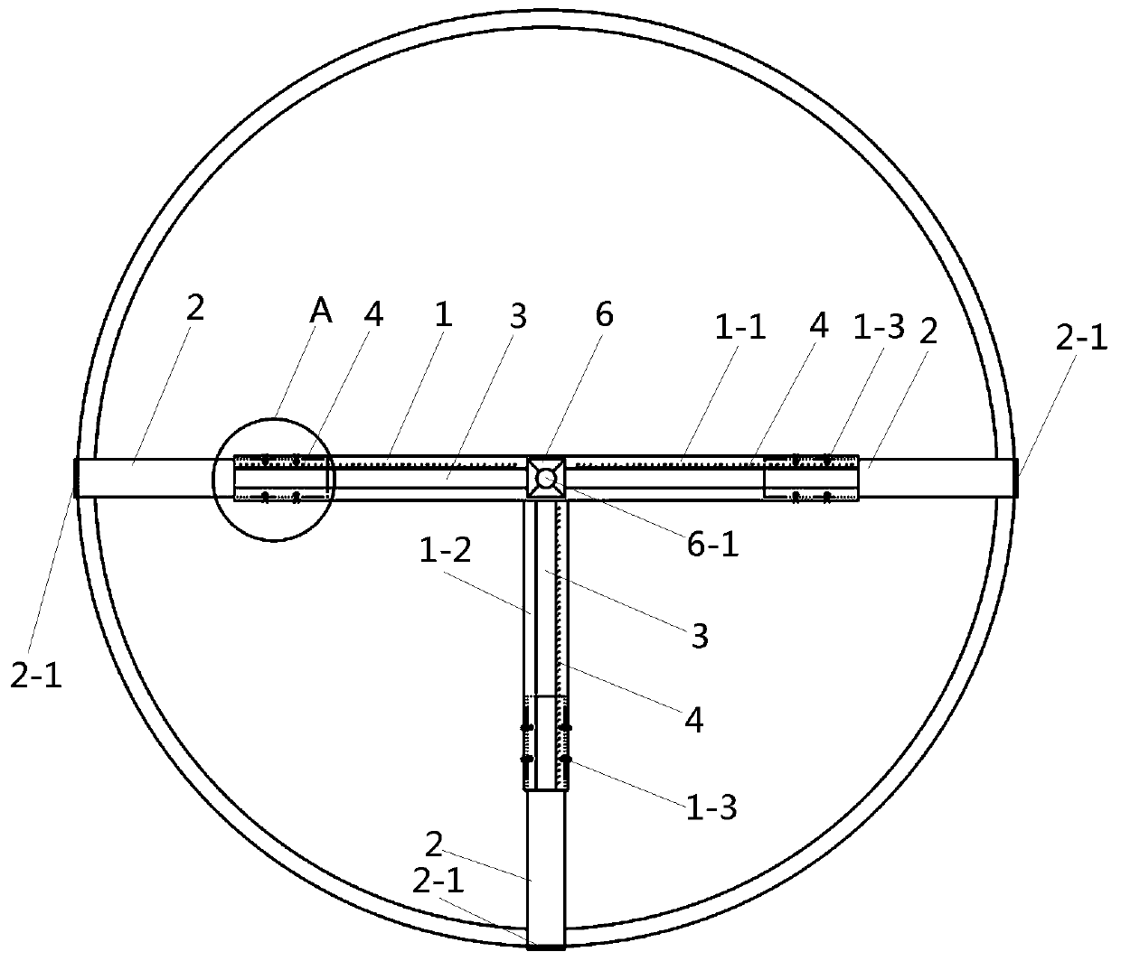
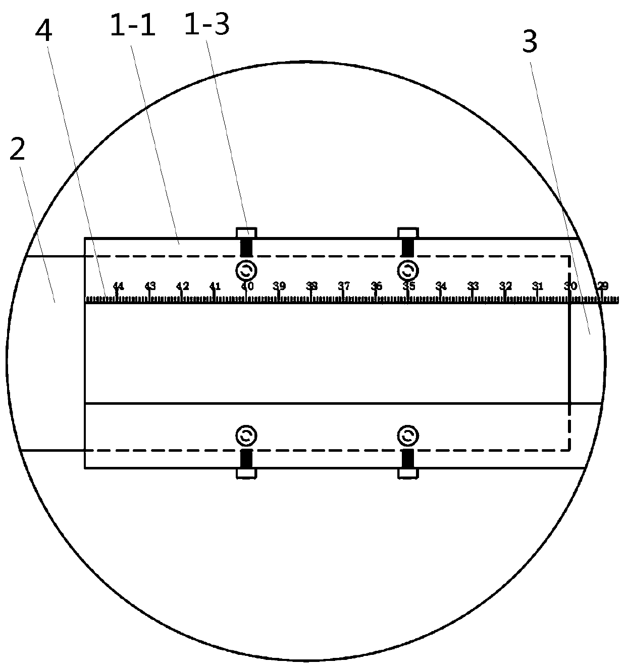
[0025] Embodiment 1, a kind of rigid steel pipe plane center positioning device and its use method, such as figure 1 As shown, it includes a storage tube 1 and a telescopic rod 2 movably arranged in the storage tube 1 . The side of the storage tube 1 is provided with a measurement port 3 , and a length scale line 4 is provided along the length direction of the measurement port 3 . The telescopic rod 2 can be stretched or retracted in the storage tube 1. By reading the corresponding position between the end of the telescopic rod 2 inserted into the storage tube 1 and the length scale line 4, the relative position of the stretched rod can be obtained conveniently and intuitively. length.

[0026] The storage tube 1 includes a main storage tube 1-1 and a secondary storage tube 1-2, one end of the secondary storage tube 1-2 is vertically connected to a position corresponding to the center of the main storage tube 1-1, and the main storage tube 1-1 1 is provided with a prism mount...

Embodiment 2

[0028] Embodiment 2, a strong-type steel pipe plane center positioning device and its use method, the end of the telescopic rod 2 is provided with a clamping plate 2-1 for clamping the outer peripheral surface of the steel pipe, and the clamping plate 2-1 is used for The outer wall of the round steel pipe 5 is clamped, which is not only convenient for operation and fixing, but also is a line contact between the clamping plate 2-1 and the outer wall of the round steel pipe 5, which can prevent the end of the telescopic rod 2 from being connected to the inner wall of the round steel pipe 5. The contact form further improves the accuracy of measurement and positioning.

[0029] Other structures of this embodiment are the same as those of Embodiment 1.

Embodiment 3

[0030] Embodiment 3, a kind of rigid steel pipe plane center positioning device and its use method, such as figure 2As shown, the storage tube 1 is a tubular profile, and the tubular profile is used as the production material, which is not only easy to obtain, simple and convenient to manufacture, but also convenient to pull the telescopic rod 2; The side wall of the cylinder 1 is provided with a positioning screw 1-3 for positioning the telescopic rod 2. By adjusting the positioning screw 1-3, not only the positioning and insertion of the telescopic rod 2 can be realized, but also the positioning and insertion of the telescopic rod 2 can be compensated. The shortcoming that the storage cylinders 1 are relatively fixed by frictional force. Using the positioning screw 1-3 for adjustment can not only ensure the convenience of drawing and inserting the telescopic rod 2, but also ensure the reliability of the fixed connection.

[0031] Other structures of this embodiment are the...


PUM


Abstract

The invention provides a strength steel pipe plane center positioning device and an application method thereof. The strength steel pipe plane center positioning device solves the technical problems inthe prior art that in a steel pipe concrete structure, steel pipe plane center positioning is inconvenient, and is low in efficiency and low in accuracy. The strength steel pipe plane center positioning device comprises an accommodating cylinder and three telescopic rods movably arranged in the accommodating cylinder. A measuring opening is formed in the lateral side of the accommodating cylinder. Length scale lines are arranged in the length direction of the measuring opening. The accommodating cylinder comprises a main accommodating cylinder and an auxiliary accommodating cylinder. One endof the auxiliary accommodating cylinder is perpendicularly connected to the center of the main accommodating cylinder. Two sets of length scale lines are arranged on the main accommodating cylinder. One set of length scale line is arranged on the auxiliary accommodating cylinder. The distances from the zero positions of the three sets of the length scale lines to the center position are consistent. A prism mounting seat is arranged at the center position. The three telescopic rods are separately inserted in two ends of the main accommodating cylinder and in the auxiliary accommodating cylinder. Positioning is convenient, accuracy is high, and measuring mounting efficiency is high.

Description

technical field [0001] The invention relates to the technical field of steel pipe concrete construction, in particular to a stiffened steel pipe plane center positioning device and a method for using the same. Background technique [0002] In the construction of concrete-filled steel tube structures, a total station is required for the adjustment of the round steel tubes. It is placed on the plane center of the steel pipe, only in this way can the measurement be carried out more accurately, and the round steel pipe can be adjusted accurately and reliably. However, without special tools, it is difficult to locate the plane center of the round steel pipe accurately. Even if the plane center of the round steel pipe is measured with conventional tools, due to the existence of measurement errors and installation errors, the construction of the prism seat is difficult to match the measured The plane centers coincide. Especially for round steel pipes with long lengths, because th...

Claims


Application Information

Patent Timeline
Patent Type & Authority Applications(China)
IPC IPC(8): G01B5/00B25B11/00
CPCG01B5/00B25B11/00
Inventor 卢春亭闫波徐前王星王鹏飞胡志曼齐建锋
Owner CHINA CONSTR SENVENTH ENG BUREAU INSTALLATION ENG
Why Eureka
Try Eureka