PIN height automatic detecting equipment

An automatic detection and high-level technology, applied in measuring devices, instruments, optical devices, etc., can solve the problems of reducing the detection efficiency of testing equipment, increasing the labor intensity of workers, and the inability of the stage to step and shift, and reduce the number of loading and unloading. , The effect of reducing labor intensity and improving detection accuracy

Pending Publication Date: 2019-04-05
昆山东卓精密电子科技有限公司
View PDF0 Cites 1 Cited by
  • Summary
  • Abstract
  • Description
  • Claims
  • Application Information

AI Technical Summary

Problems solved by technology

The CCD camera reciprocates along the X-axis or Y-axis at a time and can only detect one row of camera modules. The CCD camera is placed on the side of the stage so that the stage cannot be moved in steps. After the CCD camera reciprocates once, the detection equipment needs to pause for loading and unloading. Frequent loading and unloading not only increases the labor intensity of workers, but also reduces the detection efficiency of detection equipment

Method used


Image

  • PIN height automatic detecting equipment
  • PIN height automatic detecting equipment
  • PIN height automatic detecting equipment

Examples


Embodiment 1

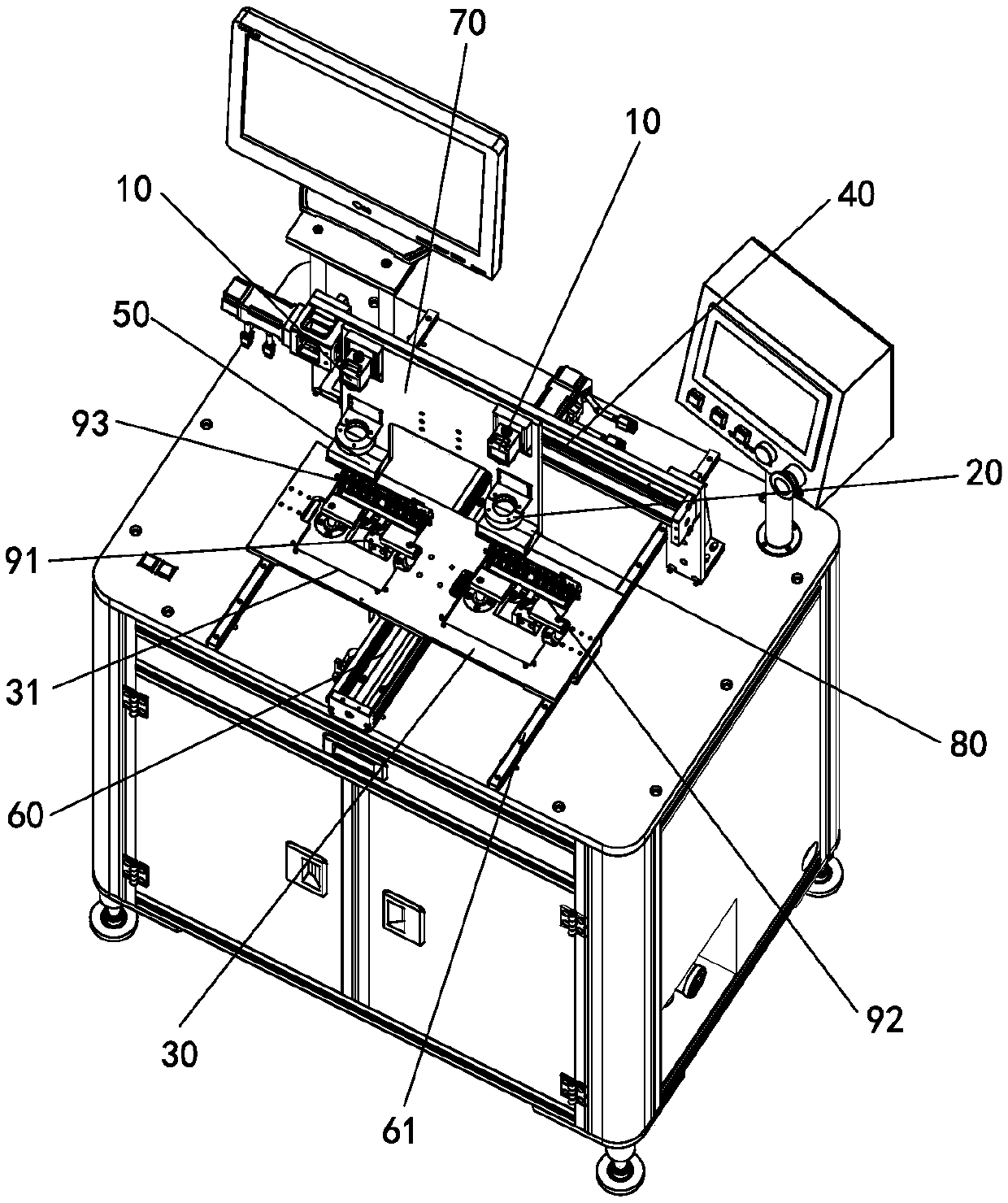
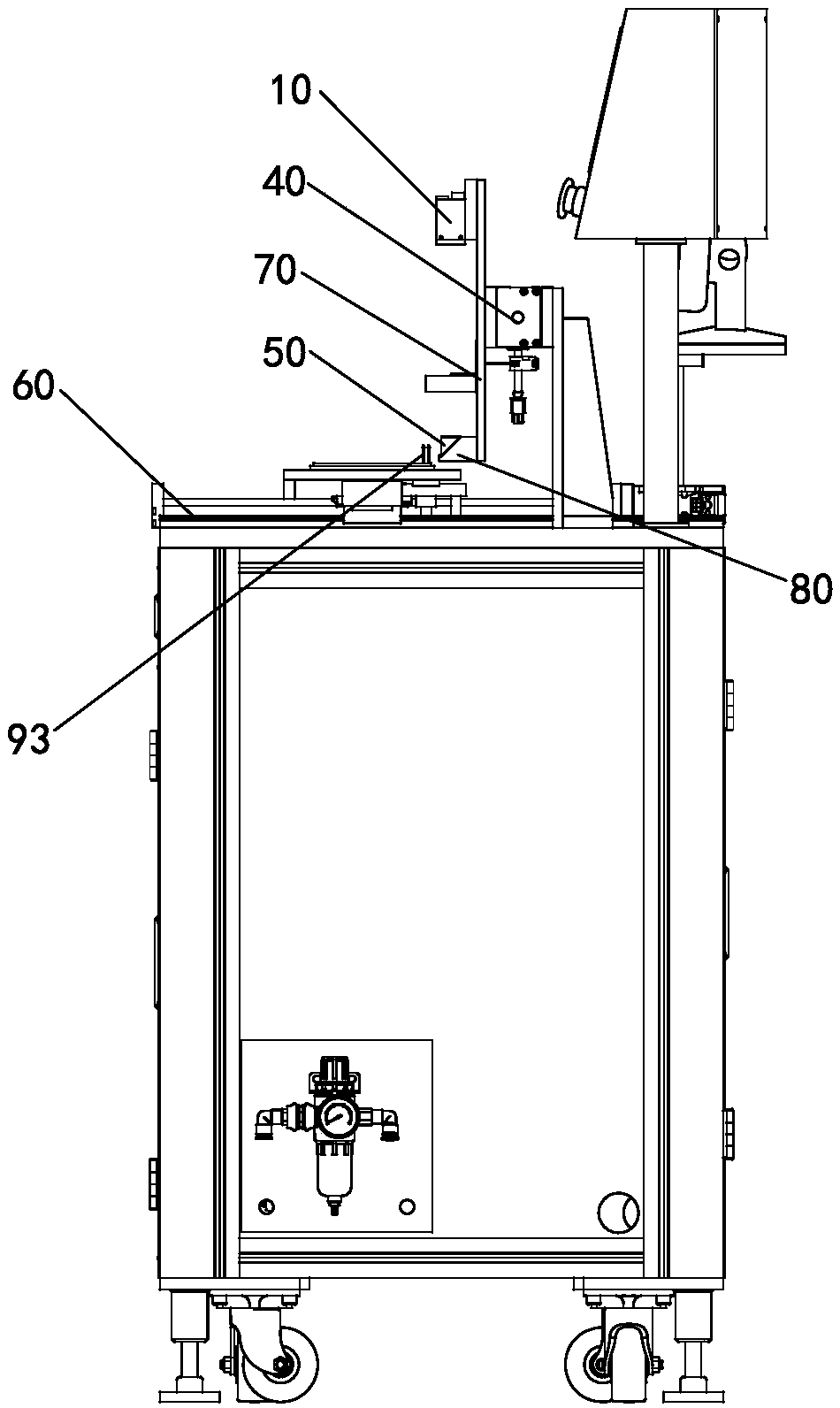
[0022] see figure 1 with 2 The PIN foot height automatic detection equipment shown is equipped with a machine vision system including two sets of CCD cameras 10 and two sets of light sources 20. In addition, the detection equipment table is also provided with a camera module The stage 30, and the first displacement mechanism 40 that drives the CCD camera 10 to move step by step.

[0023] The first displacement mechanism 40 is set up along the X-axis direction, and is erected on the top of the stage 30 by a bracket. A vertical mounting plate 70 is installed on the slider of the first displacement mechanism 40, and two groups of CCDs are fixed side by side on the mounting plate 70. side. A fixing seat 80 is respectively disposed on the mounting plate 70 below the light source 20 .

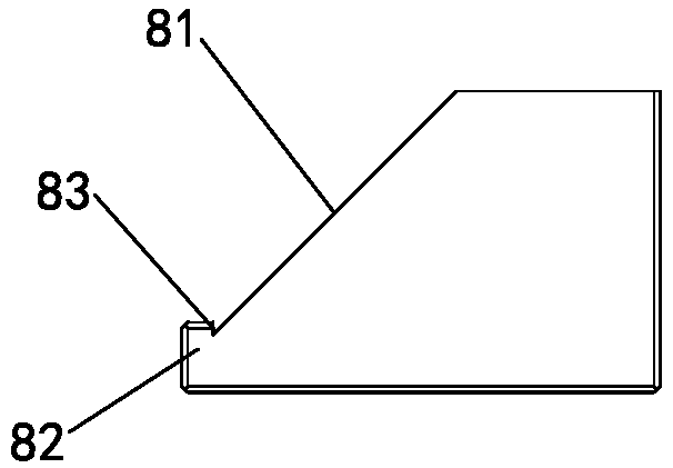
[0024] see image 3 , each fixing seat 80 has a mounting slope 81 inclined at 45°, and a stopper 82 located at the bottom of the mounting slope 81 and protruding outward, and a triangular slot 83...

Embodiment 2

[0036] The size of the camera module is small, and the PIN pin may be partially or completely submerged in the plastic frame, so that the CCD camera 10 cannot collect the side image of the PIN, so this embodiment makes further improvements on the basis of Embodiment 1 to solve the problem. this technical problem.

[0037] A pneumatic ejection mechanism for lifting the camera module from the carrier tray is provided below the carrier platform 30 . Preferably, the pneumatic ejection mechanism is composed of a cylinder 91 and a top plate 92, the top plate 92 is fixed on the top of the telescopic rod of the cylinder 91, and is located below the carrier 30; the top plate 92 is provided with four ejector pins 93 corresponding to each product.

[0038] When the camera module to be checked comes to the detection position, the cylinder 91 drives the thimble 93 to eject the camera module from the plastic frame, so that the PIN pin is completely exposed to the outside of the plastic fram...

Embodiment 3

[0041] Due to the small size of the camera module, the sudden ejection of the thimble 93 may cause the module to fall. In order to prevent this phenomenon, the thimble 93 in the second embodiment can be designed as a hollow structure, and all thimbles 93 are made of air tubes. It is connected with the vacuum generating device, and before the cylinder 91 acts, the vacuum generating device works to generate negative pressure to tightly adsorb the camera module on the thimble 93 .


PUM


Abstract

The invention provides PIN height automatic detecting equipment in order to solve the technical problem of low detecting efficiency of PIN detecting equipment in the prior art. The PIN height automatic detecting equipment is provided with a machine vision system, a carrying table and a first displacement mechanism, wherein the machine vision system includes CCD cameras and light sources, the firstdisplacement mechanism drives the CCD cameras to move in a stepping mode, the CCD cameras and the light sources are located over the carrying table and fixed to the side faces of a sliding block of the first displacement mechanism; triangular prisms with the cross sections being in isosceles triangle shapes are arranged below the CCD cameras, one of the straight faces of each triangular prism directly faces the corresponding CCD camera, the other straight face of each triangular prism directly faces PINs; and the carrying table is driven by a second displacement mechanism and operates in thedirection perpendicular to the first displacement mechanism. The total reflection phenomenon of the isosceles right-angle triangular prisms is utilized for light path turning, the CCD cameras collectimages of the side faces of the PINs from the position above the PINs, the carrying table can move in a stepping mode without blocking of the CCD cameras, after detection of one row of PINs is completed by the CCD cameras, the carrying table moves to enable the next row of camera shooting modules to arrive at the positions below the CCD cameras, and in this way, continuous detection of the multiple rows of camera shooting modules is realized.

Description

technical field [0001] The invention relates to the technical field of camera module production equipment, and mainly relates to camera module PIN foot detection equipment. Background technique [0002] The PIN pin height detection of the camera module has always used the detection equipment based on the machine vision system. The CCD camera is placed on the side of the carrier and takes pictures of the PIN pin from the side. The machine vision system compares the photos taken by the CCD camera with the pre-stored photos in the system. Determine whether the height of the PIN pin is within the tolerance range. The CCD camera reciprocates along the X-axis or Y-axis at a time and can only detect one row of camera modules. The CCD camera is placed on the side of the stage so that the stage cannot be moved in steps. After the CCD camera reciprocates once, the detection equipment needs to pause for loading and unloading. Frequent loading and unloading not only increases the labor...

Claims


Application Information

Patent Timeline
Patent Type & Authority Applications(China)
IPC IPC(8): G01B11/06
CPCG01B11/0608
Inventor 陈洪虎
Owner 昆山东卓精密电子科技有限公司
Why Eureka
Try Eureka