Wide range platinum resistor temperature sampling circuit
A technology of sampling circuit and platinum resistance, applied in thermometers, thermometers using electric/magnetic elements that are directly sensitive to heat, and electric devices, can solve problems such as troubles, improve accuracy, overcome voltage divider resistance mismatch, The effect of high-precision temperature sampling
- Summary
- Abstract
- Description
- Claims
- Application Information
AI Technical Summary
Problems solved by technology
Method used
Image

Examples
Embodiment 1
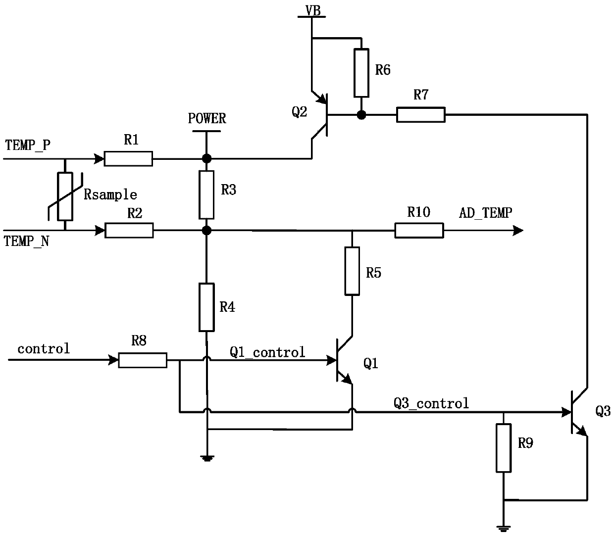
[0028] image 3Shown is the equivalent circuit diagram of the temperature sampling circuit when the PT100 temperature sensor is connected, the processor chip sends the PT100_control control signal, the high level is active, the first transistor Q1 and the third transistor Q3 are NPN transistors, so that It works in the saturation region. When PT100_control outputs a high level, the base-emitter of the first triode Q1 and the third triode Q3 are forward-biased, the two triodes are turned on, the voltage of the power supply VB is 5V and the power supply VB is pulled up through the base of Q2 Resistor R6, Q3 collector load resistor R7 and the third transistor Q3 form a loop, Q2 base pull-up resistor R6, Q3 collector load resistor R7 can be regarded as the collector load resistor of the third transistor Q3, the first The collector current of the triode Q3 is:
[0029]
[0030] In the formula, V ce_Q3 is the collector-emitter saturation turn-on voltage drop of the third trans...
Embodiment 2
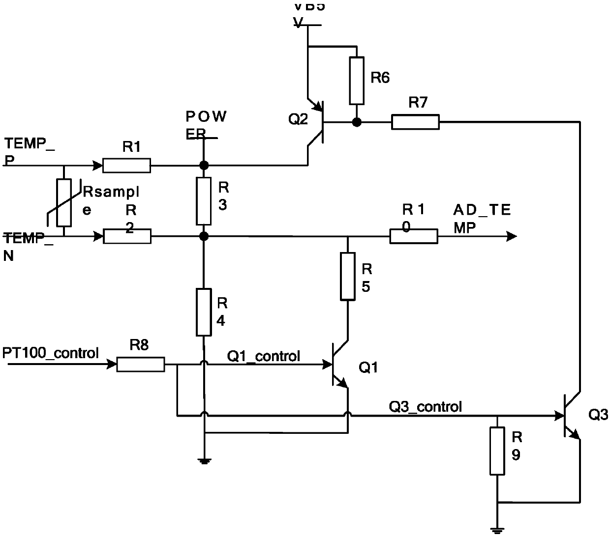
[0038] Figure 4 Shown is the equivalent circuit diagram of the temperature sampling circuit when the PT1000 temperature sensor is connected, its principle is similar to that of PT100, the control signal of the PT1000 temperature sensor is sent by the processor chip, the third transistor Q3 is turned on, and the current flow of the turn-on loop Through the base of the second transistor Q2, the second transistor Q2 is turned on, and the internal power supply POWER terminal is pulled up; at this time, V VB =8V, according to the formula (1), (2), (3) to get V POWER ,
[0039]
[0040] At this time, the temperature sampling value V can be calculated by formula (5) AD_TEMP .
[0041] The temperature sampling circuit of the present invention is set by the third triode Q3, the second triode Q2 and the Q2 base pull-up resistor R6, the Q3 collector load resistor R7, the base current limiting resistor R8, and further through the first three The transistor Q1 and Q1 collector load...
PUM
 Abstract
Description
Claims
Application Information
 - R&D
- Intellectual Property
- Life Sciences
- Materials
- Tech Scout
- Unparalleled Data Quality
- Higher Quality Content
- 60% Fewer Hallucinations
Browse by: Latest US Patents, China's latest patents, Technical Efficacy Thesaurus, Application Domain, Technology Topic, Popular Technical Reports.
© 2025 PatSnap. All rights reserved.Legal|Privacy policy|Modern Slavery Act Transparency Statement|Sitemap|About US| Contact US: help@patsnap.com