High-temperature stress oxidation testing system

A testing system and stress testing technology, applied in the direction of using stable bending force to test material strength, using stable tension/pressure to test material strength, measuring device, etc., can solve the problem of low single test cost and single test cost High, poor device scalability, etc., to achieve the effects of low single test cost, reduced number of tests, and high utilization rate

Pending Publication Date: 2019-04-05
ZHEJIANG ZHENENG TECHN RES INST
View PDF0 Cites 4 Cited by
  • Summary
  • Abstract
  • Description
  • Claims
  • Application Information

AI Technical Summary

Problems solved by technology

[0004] The technical problem to be solved and the technical task proposed by the present invention are to solve many problems in the existing high-temperature stress oxidation test device, such as poor device expandability, high-temperature oxidation test only, low utilization rate, and high single test cost. A high-temperature stress oxidation test system, the system can complete multiple high-temperature stress oxidation tests such as tension, bending and compression, and the system has good scalability, high utilization rate, and low single test cost

Method used


Image

  • High-temperature stress oxidation testing system
  • High-temperature stress oxidation testing system
  • High-temperature stress oxidation testing system

Examples


Embodiment 1

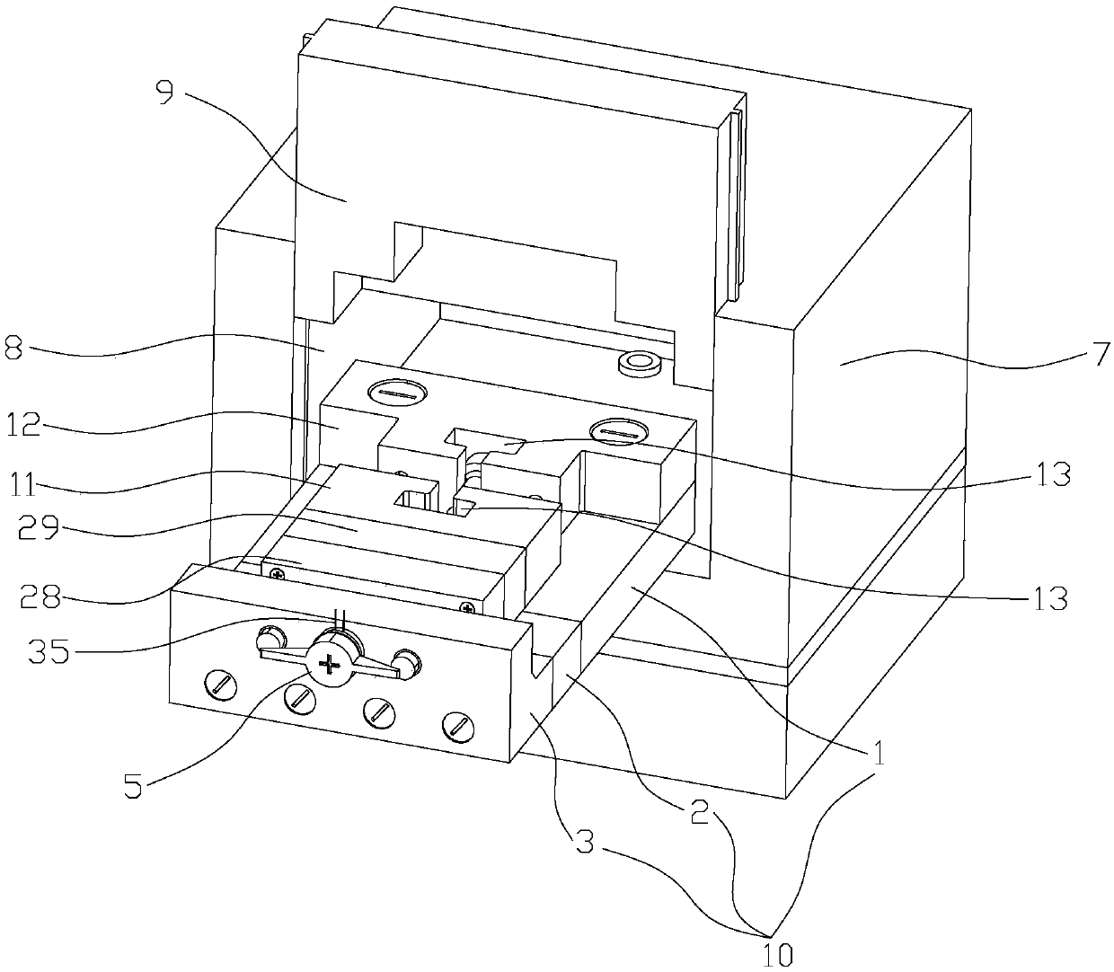
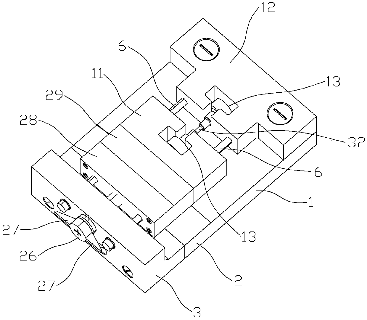
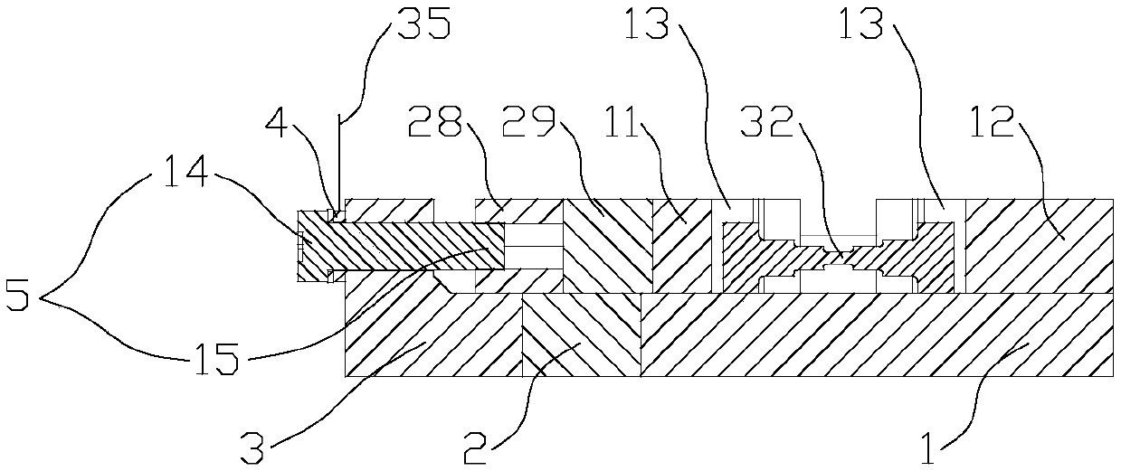
[0025] Example 1 as Figure 1~3 As shown, a high-temperature stress oxidation test system includes a heating furnace 7 with an inlet 8 and a furnace door 9, a stress testing device and a stress applying device that can be placed in the heating furnace 7. The heating furnace 7 is pasted with heat-insulating cloth on the edge of the inlet 8 (not shown in the figure), the stress testing device includes a pressure display and a pressure sensor 4 connected by a wire 35, the pressure sensor 4 in this embodiment is a high-temperature film pressure sensor, and the stress applying device includes a base 10 and a detachable And the clamp to be replaced is a tensile clamp in this embodiment, and the base 10 is a detachable structure, which is composed of the front base 3, the base heat insulation block 2 and the rear base 1, which are fixed by bolts from front to back in the horizontal direction; An adjustment bolt 5 is rotated on the front base 3, and one end of the adjustment bolt 5 is...

Embodiment 2

[0027] Example 2 as Figure 4~5 The compression test is performed as shown, and the difference from Example 1 is that the clamp is replaced by a compression clamp for compression testing, the tension slider 28 is replaced by a compression slider 30, and the tension slide clamp 11 is replaced by a compression slide clamp 16. The tensile clamp 12 is replaced by a compression clamp 17; the clamping structure between the compression slide clamp 16 and the compression clamp 17 includes two compression clamps 16 and 17 that are against the end of the workpiece to be measured. Top clamp 18, the connecting line direction of two top clamps 18 is parallel to the translation direction of compression slide block 30; Described front base 3 is provided with the screw hole that matches with threaded section 15, and the threaded section 15 of adjusting bolt 5 one ends passes through screw hole. The hole is against the compression slider 30, and the compression slider 30 is provided with a but...

Embodiment 3

[0029] Example 3 as Figure 6~7 The shown system performs the bending test. The difference from Embodiment 1 is that the fixture is replaced by a bending fixture for the bending test, and the stretching slider 28 is replaced by the bending slider 31. The bending slider and the compression slider are common, and the pulling The extended sliding clip 11 is replaced by a curved sliding clip 19, and the stretching fixed clip 12 is replaced by a curved fixed clip 20; the clamping structure between the curved sliding clip 19 and the curved fixed clip 20 includes a convex part 21 and a flat part 22 and three cylindrical pins 23. The positions of the convex part and the flat part can be interchanged. In this embodiment, it is preferable that the convex part 21 is set on the bending sliding clip 19, and the flat part 22 is set on the bending fixing clip 20. A cylindrical pin 23 is used in the bending test as shown in the figure. Set on the side of the convex part 21 and vertically clam...


PUM


Abstract

The invention relates to the field of mechanical testing, in particular to a high-temperature stress oxidation testing system. An existing high-temperature stress oxidation test device has poor expansibility, low utilization rate and high single testing cost. The high-temperature stress oxidation testing system comprises a heating furnace with an inlet and a furnace door, a stress testing device and a stress application device which can be put into the heating furnace, wherein the stress testing device comprises a pressure display and a pressure sensor which are connected by wires, and the pressure sensor is arranged on the stress application device. The stress application device drives a sliding block to move transversely by the rotation of an adjusting bolt, so that a clamp is loaded onthe workpiece to be tested in the horizontal direction, and tensile, bending and compression tests corresponding to the clamp are completed; the tensile, bending and compression tests only need to bedismounted and replaced with the corresponding clamp, and other parts can be used universally; and the testing system has good expansibility, high utilization rate and low single test cost.

Description

technical field [0001] The invention relates to the field of mechanical testing, in particular to a high-temperature stress oxidation testing system. Background technique [0002] High temperature stress oxidation is a delayed failure phenomenon of metal components under load in high temperature air, water vapor and other environments. The interaction between stress and environment will accelerate the oxidation process of materials. The intergranular cracks of stress oxidation generated in grain boundaries are the One of the main reasons for the failure of metal materials, the high temperature stress oxidation test is an important means to study the stress oxidation process and service performance of materials under high temperature conditions. At present, a large number of high-temperature oxidation experiments are tested under static and stress-free conditions. Under static and stress-free conditions, many alloys are prone to produce oxide films on the surface to prevent f...

Claims


Application Information

Patent Timeline
Patent Type & Authority Applications(China)
IPC IPC(8): G01N3/02G01N3/18G01N3/20
CPCG01N3/02G01N3/18G01N3/20
Inventor 王超俞昌宸楼玉民赵宁宁彭以超鲍听赵炜炜
Owner ZHEJIANG ZHENENG TECHN RES INST
Why Eureka
Try Eureka