
High energy accelerator CT rock mechanics test system

A technology of rock mechanics and test system, which is applied in the direction of using stable tension/pressure to test the strength of materials, instruments, scientific instruments, etc. The effect of precision control and improved rotational stability

Active Publication Date: 2020-02-14
INST OF GEOLOGY & GEOPHYSICS CHINESE ACAD OF SCI
View PDF18 Cites 0 Cited by
  • Summary
  • Abstract
  • Description
  • Claims
  • Application Information

AI Technical Summary

Problems solved by technology

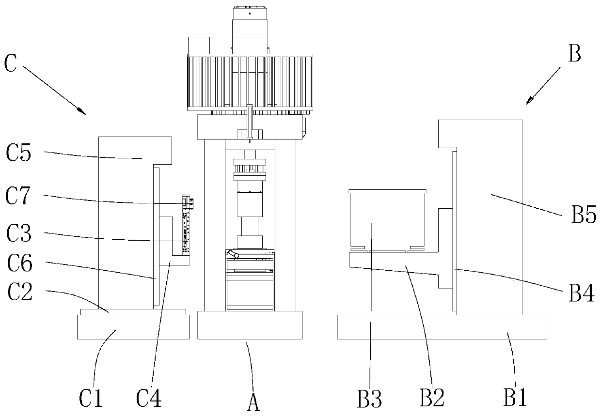
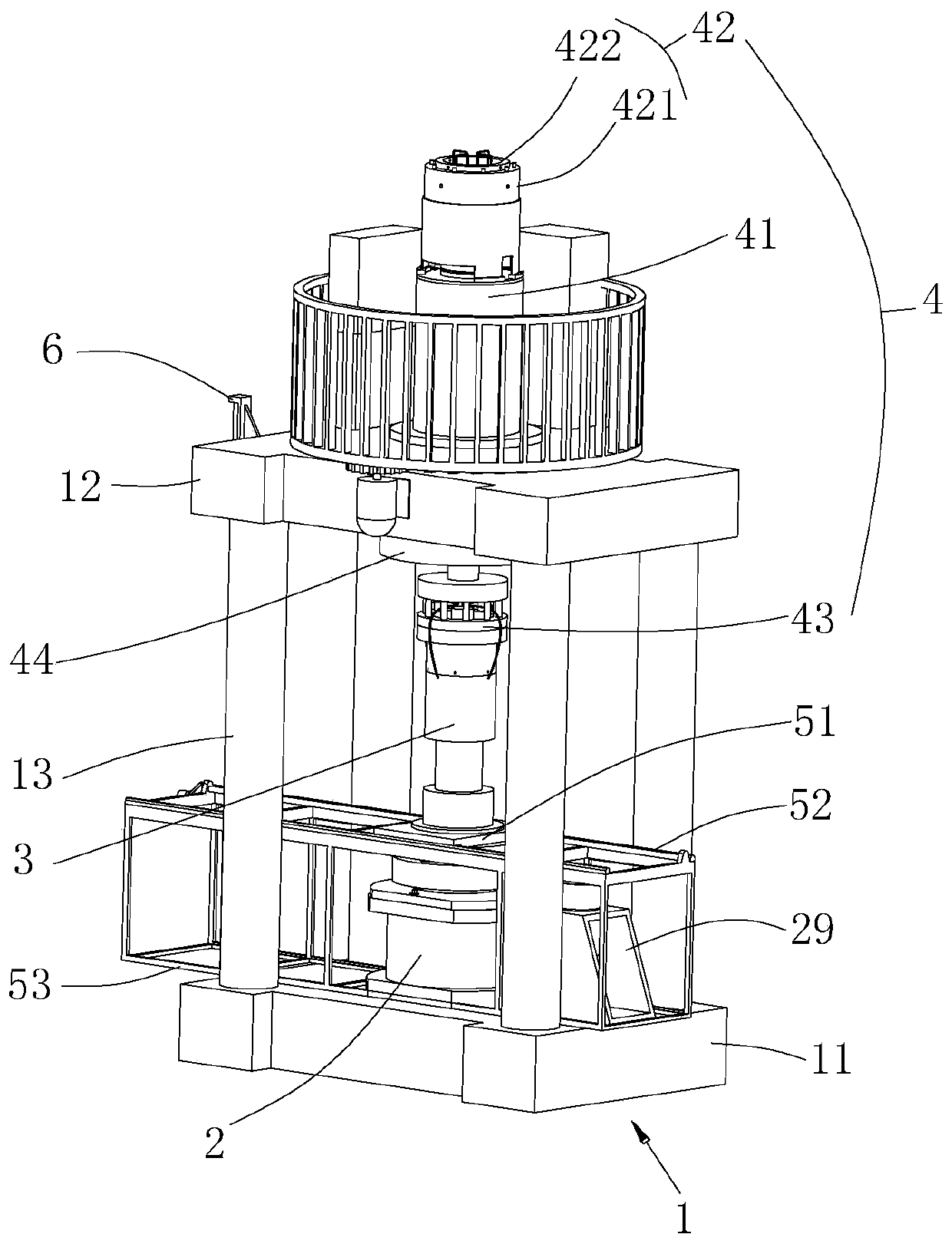
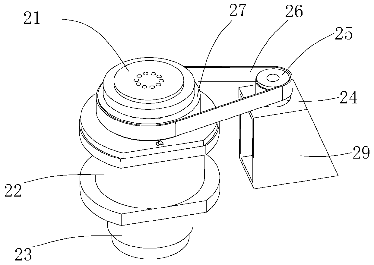
[0006] In order to solve the above-mentioned problems in the prior art, that is, in order to solve the problem that the existing rock mechanics test system performs CT scanning after the rock sample is unloaded, resulting in that the CT imaging cannot fully reflect the structural state of the rock sample when loading, the present invention A high-energy accelerator CT rock mechanics test system is provided, the high-energy accelerator CT rock mechanics test system includes a mechanical testing machine, a high-energy accelerator CT ray source and a detector, and the mechanical testing machine is arranged between the high-energy accelerator CT ray source and the Between the detectors, the mechanical testing machine includes a fixed member, a rotating device and a pressure chamber, the rotating device is arranged on the fixed member, the pressure chamber is connected with the rotating device, and when testing, Driven by the rotating device, the pressure chamber can rotate relative to the fixed member

Method used


Image

  • High energy accelerator CT rock mechanics test system
  • High energy accelerator CT rock mechanics test system
  • High energy accelerator CT rock mechanics test system

Examples


Embodiment Construction

[0026] First of all, those skilled in the art should understand that these embodiments are only used to explain the technical principles of the present invention, and are not intended to limit the protection scope of the present invention. For example, although the various parts of the test system in the drawings are drawn in a certain scale, this proportional relationship is not static, and those skilled in the art can adjust it according to needs, so as to adapt to specific applications.

[0027] It should be noted that, in the description of the present invention, terms such as "center", "upper", "lower", "top", "bottom", "inner", "outer" and other indicated directions or positional relationships are Based on the orientation or positional relationship shown in the drawings, this is only for convenience of description, and does not indicate or imply that the device or element must have a specific orientation, be constructed and operated in a specific orientation, and therefor...


PUM


Abstract

The invention belongs to the technical field of mechanics test devices, and specifically relates to a high-energy accelerator CT rock mechanics test system. The high-energy accelerator CT rock mechanics test provided by the invention comprises a mechanics test machine, a high-energy accelerator CT ray source and a detector, the mechanics test machine is arranged between the high-energy acceleratorCT ray source and the detector, the mechanics test machine comprises a fixed component, a rotary apparatus and a pressure chamber, the rotary apparatus is arranged on the fixed component, the pressure chamber is connected with the rotary apparatus, and when a test is executed, the pressure chamber can rotate relative to the fixed component under driving of the rotary apparatus. The test machine is provided with the rotary apparatus, and when the test is executed, the pressure chamber is driven by the rotary apparatus to rotate, namely, a test sample can be scanned in a process in which a loadtest is executed for the test sample, consequently, CT imaging can completely reflect a structural state of the test sample when the test sample is loaded, and scientific researches are facilitated more.

Description

technical field [0001] The invention belongs to the technical field of mechanical testing equipment, and specifically provides a high-energy accelerator CT rock mechanical testing system. Background technique [0002] The exploration and development of resources in the world today has advanced to the second deep space of the earth (2000-10000 meters). The development of such resources requires the use of ultra-deep vertical wells and horizontal wells, and it is necessary to reform the geological body of the reservoir and implement rock fracturing to increase permeability. . The efficient development of this kind of resources must solve the major basic scientific problems "the formation and evolution of geological bodies under the action of pressure and temperature, the law of gas-liquid migration and the characteristics of physical property changes", which is also the frontier science for understanding the state of geological bodies and geological processes question. [00...

Claims


Application Information

Patent Timeline
Patent Type & Authority Patents(China)
IPC IPC(8): G01N3/12G01N23/04
CPCG01N3/12G01N23/04G01N2203/0003G01N2203/0019G01N2203/0048G01N2203/006G01N2203/0075G01N2203/0647G01N2223/03G01N2223/1016G01N2223/607
Inventor 李晓李守定史戎坚赫建明郑博
Owner INST OF GEOLOGY & GEOPHYSICS CHINESE ACAD OF SCI
Learn More