Fluid energy turbine machine

A technology of fluid energy and turbines, which is applied to mechanical equipment, engine components, variable displacement engines, etc., and can solve problems such as failure to become a power machine and low energy

Inactive Publication Date: 2012-08-01
朱剑文
View PDF1 Cites 8 Cited by
  • Summary
  • Abstract
  • Description
  • Claims
  • Application Information

AI Technical Summary

Problems solved by technology

But the energy provided by water evaporation is too small to be a power machine

Method used


Image

  • Fluid energy turbine machine
  • Fluid energy turbine machine
  • Fluid energy turbine machine

Examples


Embodiment Construction

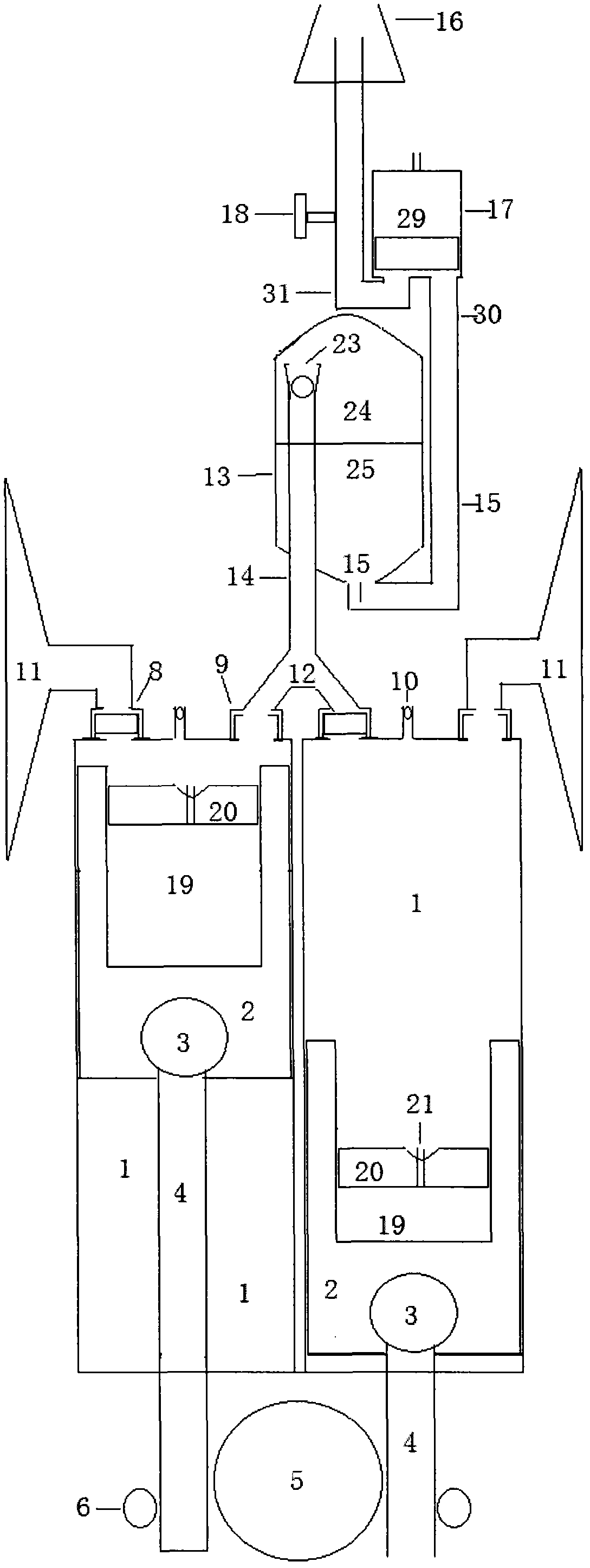
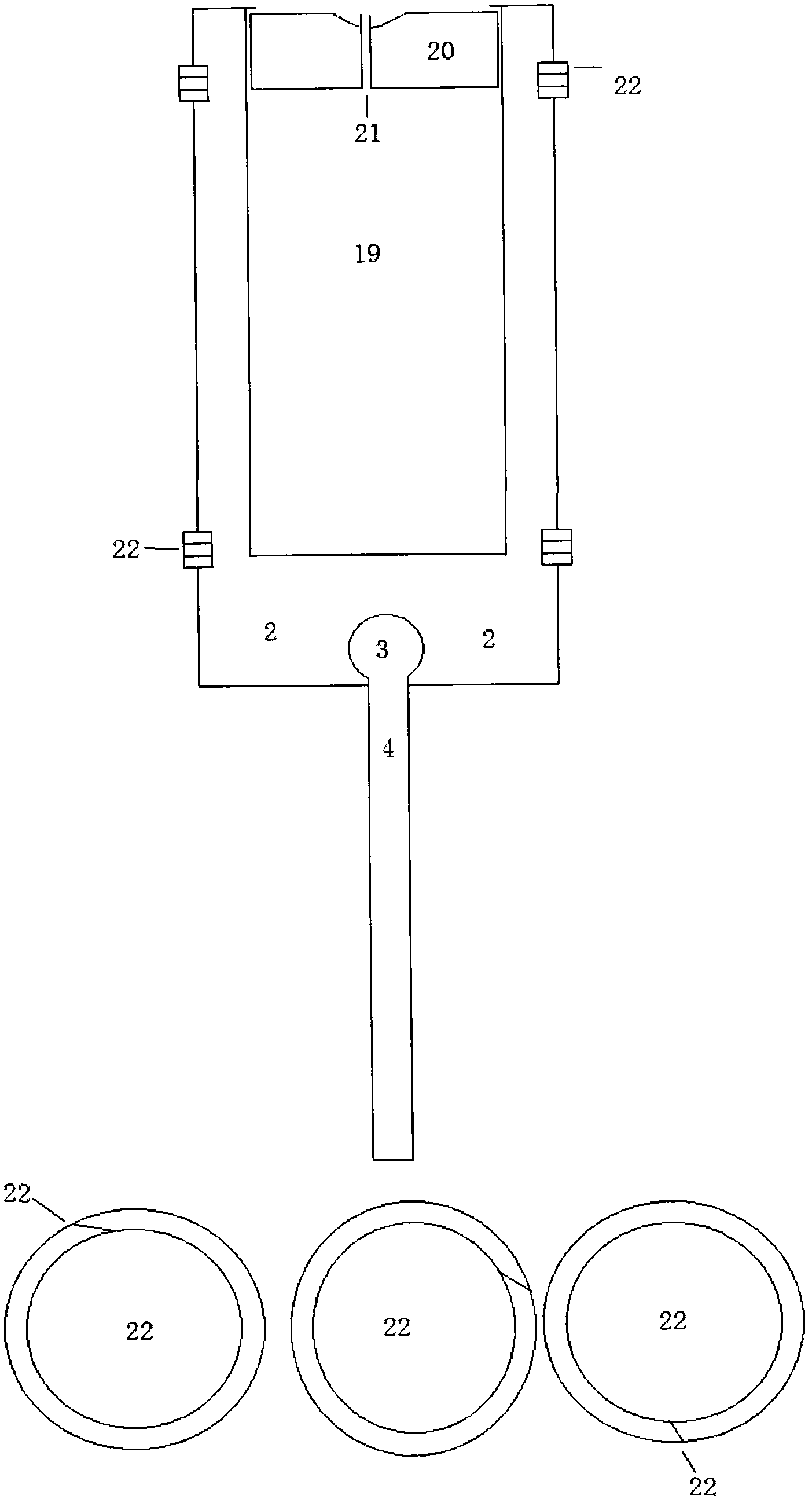
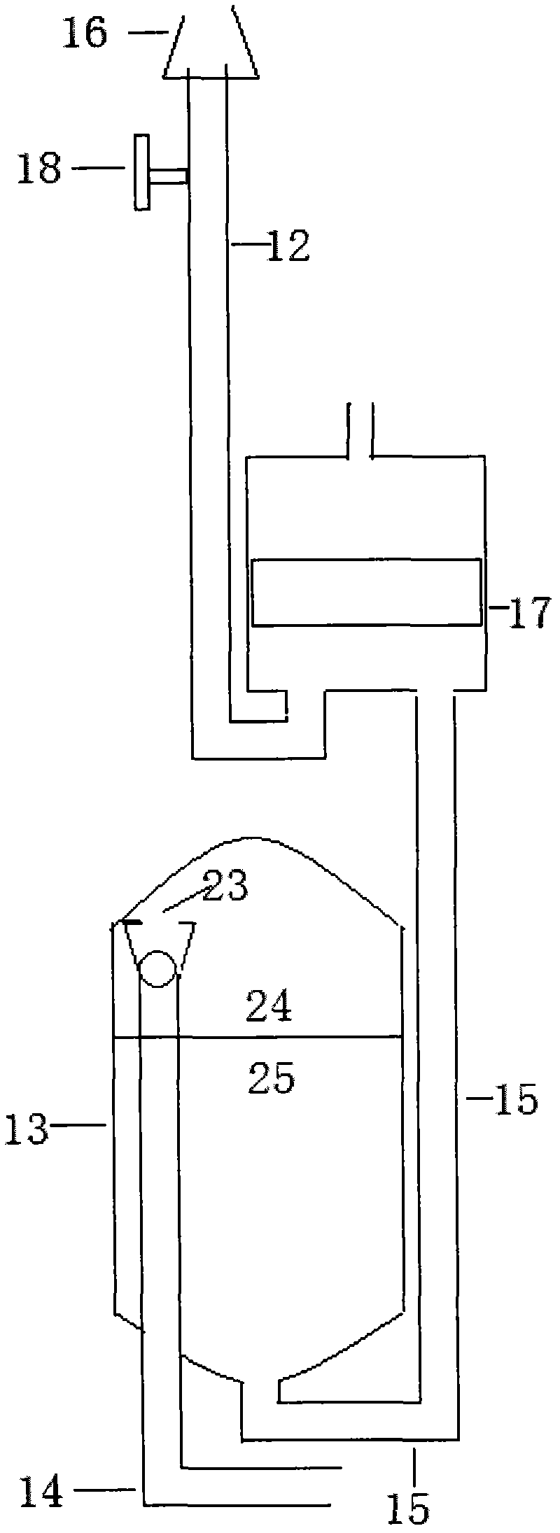
[0024] 1. The fluid energy turbine can work independently by using the atmospheric pressure difference: the fluid energy turbine is placed on the ground or fixed at the bottom of a skyscraper. The exhaust pipe of the fluid energy turbine is not additionally used to communicate with the water pressure pressure converter or the one-way ball valve made of a very light ball at the inlet of the water pressure pressure converter without additional use. The higher the power, the greater the power. The outer outlet of the end of the exhaust pipe is additionally equipped with a single Venturi tube cyclone decompression cover that produces the effect of ejection increase. Use a special tool to preset air or other negative pressure gas with high compression ratio, difficult to dissolve, heat generation, moisture-free inert gas (such as nitrogen) to the compressed gas energy storage chamber through the inlet valve. According to the height of the fluid energy turbine exhaust pipe and other...


PUM


Abstract

The invention discloses a new energy power machine, and particularly relates to a fluid energy turbine machine, which is provided with an existing or improved cylinder and piston turbine machine body, has or does not have a connecting rod and crank mechanism, is additionally provided with an improved piston, a fluid inlet supercharging structure, a fluid drainage decompressing structure, a steam pressure conversion output and an output pressure adjusting structure, independently or integrally uses energy in fluid work media in various energy states, and converts the energy into mechanical energy or energy in other forms so as to work continuously. The existing or improved cylinder and piston turbine machine body absorb the energy of fluid in various energy states and realizes steam pressure conversion, and is a core for connection and energy output of other various structures. The additional improved piston absorbs energy of a fluid hammer. By the aid of the fluid inlet supercharging structure and the fluid drainage decompressing structure, fluid entering a fluid work cylinder rotates to generate supercharging vortex, and fluid drained from the fluid work cylinder rotates to generate homodromous decompression vortex. A vertical steam pressure conversion structure leads fluid to be drained out of the turbine machine body smoothly after the fluid finishes acting by the aid of steam pressure conversion.

Description

Technical field: [0001] The present invention relates to: a new energy power machine, especially with existing or improved fluid working cylinder piston turbine body, with or without connecting rod and crankshaft mechanism, additional improved piston, additional inlet fluid pressurization and exhaust fluid decompression , additional water pressure conversion output and output pressure adjustment structure, used alone or in combination to convert the energy contained in various energy state fluid working fluids into mechanical energy or other forms of energy to continuously work fluid energy turbines. Background technique: [0002] At present, the known water energy collectors include water hammer pumps, turbines, hydroelectric power stations, and tidal power stations. Although they are all green energy sources, they can only collect the potential energy pressure of dynamic water. The construction of a dam has high requirements on topography and geology and other conditions, ...

Claims


Application Information

Patent Timeline
Patent Type & Authority Applications(China)
IPC IPC(8): F01B7/14F01B1/02F01B9/04F01B31/00F03C1/007F03C1/02F03C1/28
Inventor 朱剑文
Owner 朱剑文
Why Eureka
Try Eureka