Ontrack self-correction positioning method based on optical images

A positioning method and optical image technology, applied to satellite radio beacon positioning systems, measuring devices, instruments, etc., can solve problems such as decreased positioning accuracy, positioning failure, and positioning parameter offset, so as to improve timeliness and positioning accuracy , reducing the effect of time-varying error sources

Active Publication Date: 2019-04-05
SHANGHAI AEROSPACE COMP TECH INST
View PDF25 Cites 1 Cited by
  • Summary
  • Abstract
  • Description
  • Claims
  • Application Information

AI Technical Summary

Problems solved by technology

[0002] With the cooperation of ground control point information, the current on-orbit positioning based on optical images has been able to obtain high positioning accuracy, but in some occasions (on the sea) it is not easy to obtain ground control point information. It is also impossible to achieve real-time correction of ground control points, so how to achieve high-precision on-orbit positioning without control points (or calibration of a small number of control points) is an urgent technical problem to be solved
[0003] When performing on-orbit positioning based on optical satellite images, due to the existence of various time-varying errors in the system (deformation caused by temperature, orbital drift, elevation change, etc.), the positioning parameters will deviate from the calibration value after the system has been working for a certain period of time, resulting in positioning errors. Accuracy drops
In this case, if there is no ground control point (for example, no effective ground control point can be found on the sea) to re-calibrate, it will cause the positioning to fail

Method used


Image

  • Ontrack self-correction positioning method based on optical images
  • Ontrack self-correction positioning method based on optical images
  • Ontrack self-correction positioning method based on optical images

Examples


Embodiment Construction

[0029] Hereinafter, the present invention will be further described in detail through specific embodiments in conjunction with the drawings.
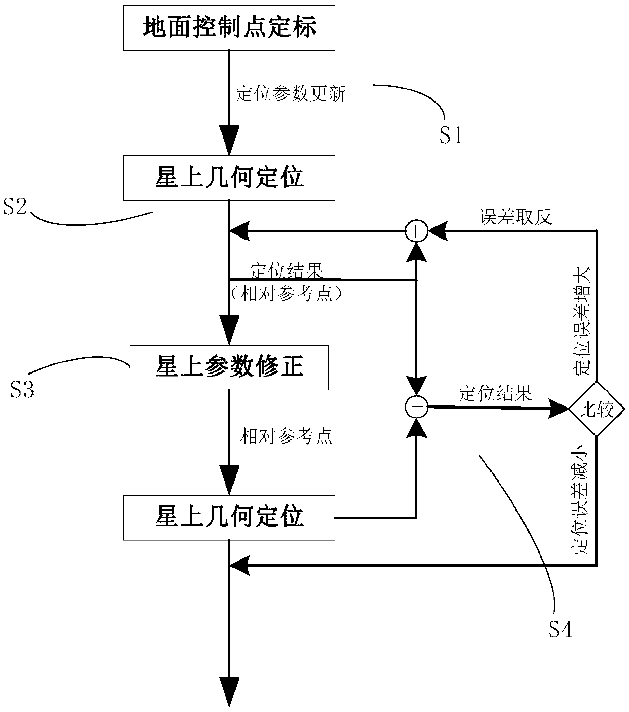
[0030] The basic idea of ​​the present invention is: firstly, dual DSPs (first DSP and second DSP) are used for parallel processing. The first DSP processes the positioning directly, and transmits the positioning results to the second DSP as a relative "control point". Use the relative "control point" information to correct the current on-satellite geometric positioning model parameters. After the correction, use the point with the same name to judge the rationality of the correction result. Once the correction result is judged to be reasonable, the correction result is transmitted to the first DSP. Update the positioning parameters and iterate in turn to eliminate the time-varying errors of the system; at the same time, the relative reference points can be used to compensate for the errors caused by elevation changes.

[0031] Specifically,...


PUM


Abstract

The invention provides an ontrack self-correction positioning method based on optical images. The ontrack self-correction positioning method comprises the steps: relevant parameters of a geometric positioning model on a satellite are calibrated through ground control point information, and the calibrated relevant parameters are marked on the satellite; direct positioning is conducted through the geometric positioning model on the satellite by combining with the calibrated relevant parameters, and the positioning result serves as a relative control point of a next frame of data; self-correctionis conducted on the relevant parameters through the relative control point; and whether the self-correction result is reasonable or not is judged, and if the self-correction result is reasonable, therelevant parameters are updated through the self-correction result. A system time-varying error source can be reduced without a ground control point, and the positioning precision is improved; through circulative iteration, influences of elevation change on the positioning precision can be eliminated, and thus elevation library information does not need to be stored during ontrack processing; andthrough double-DSP parallel processing, positioning timeliness can be improved greatly.

Description

Technical field [0001] The invention relates to a target positioning detection technology in the field of optical satellite remote sensing images, in particular to an on-orbit self-correcting positioning method based on optical images. Background technique [0002] With the cooperation of ground control point information, the current on-orbit positioning based on optical images can achieve high positioning accuracy. However, it is not easy to obtain ground control point information on some occasions (on the sea surface). It is also impossible to make real-time correction of ground control points. Therefore, how to achieve high-precision on-orbit positioning without control points (or calibration of a small number of control points) is a technical problem that needs to be solved urgently. [0003] When performing on-orbit positioning based on optical satellite images, due to various time-varying errors in the system (temperature-induced deformation, orbit drift, elevation change, et...

Claims


Application Information

Patent Timeline
Patent Type & Authority Applications(China)
IPC IPC(8): G01S19/23
CPCG01S19/23
Inventor 张宇韩传钊谢宝蓉丁荣莉李杰冯书谊
Owner SHANGHAI AEROSPACE COMP TECH INST
Why Eureka
Try Eureka