

A flexible mechanism topology optimization design method based on adaptive constraint
A topology optimization and flexible mechanism technology, applied in constraint-based CAD, design optimization/simulation, calculation, etc., can solve problems such as single hinges
- Summary
- Abstract
- Description
- Claims
- Application Information
AI Technical Summary
Problems solved by technology
Method used
Image

Examples
Embodiment 1
[0074] The present invention provides a flexible mechanism topology optimization design method based on adaptive constraints, see Figure 11 , including the following steps:
[0075] S1: Given the initial design area, divide the finite element grid, and give boundary conditions, load cases and other conditions.
[0076] S2: Read the fixed finite element grid model file of the design area, read the current structure reserved element data file, form a layer of artificial material elements with small topological variable values around the structure and holes, and automatically form the current effective structure limited The meta-model generates and saves the mapping relationship data file between the grid model of the largest design area and the effective grid model of the current structure.
[0077] S3: Apply unit virtual load at the output end, and perform finite element analysis to obtain displacement vector data under actual load and unit virtual load. By reading the map...
Embodiment 2
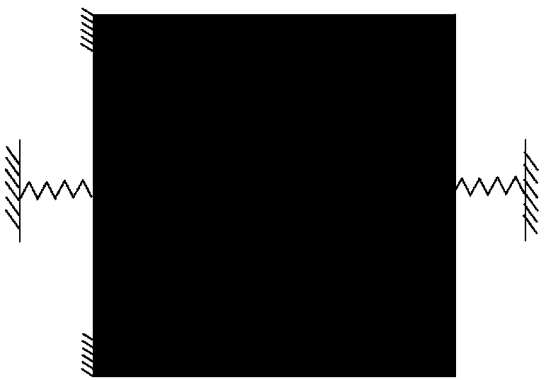
[0099] This embodiment proposes a single-input single-output displacement reverse flexible mechanism, the size of the initial mechanism is 0.4m×0.4m×0.05m, and the elastic modulus of the material is 2.09×10 14 pa, Poisson's ratio is 0.3. The upper and lower parts on the left side of the mechanism are fixed-end constraints, the input force acts on the left midpoint, its magnitude is 20000N, the direction is rightward, and the stiffness is 2.0×10 8 The N / m spring replaces the workpiece that the input end is in contact with the mechanism; the middle point on the right is the displacement output end, and the stiffness is 2.0×10 8 The N / m spring replaces the workpiece where the output end is in contact with the mechanism, figure 1 It is a schematic diagram of the initial design domain, force and boundary conditions of the displacement inversion mechanism. figure 1 where F is the force acting on the input. The goal of the optimal design of this example is to maximize the displace...
Embodiment 3
[0101] This embodiment proposes a micro-clamping mechanism, the design domain size of the mechanism is 500 μm × 500 μm × 10 μm, and the elastic modulus of the material is 1.9 × 10 11 pa, Poisson's ratio is 0.3. The upper and lower parts on the left side of the mechanism are fixed-end restraints, the input force acts on the midpoint on the left side, the size is 0.1mN, and the workpiece with the input end and the mechanism is replaced by a spring with a stiffness of 10.0N / m; the size of the gap on the right side is 100μm ×100μm, the upper and lower points of the notch are the displacement output ends, and the springs with a stiffness of 1000.0N / m are used to replace the workpieces in contact with the mechanism at the output end. Figure 4 It is a schematic diagram of the initial design domain, force and boundary conditions of the micro-clamping mechanism. The optimal design goal of this example is to maximize the absolute value of the difference between the two displacements a...
PUM
 Abstract
Description
Claims
Application Information