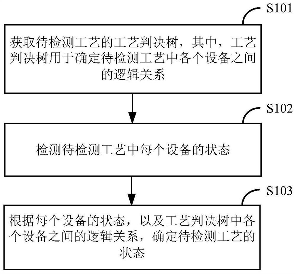
[0006] An embodiment of the present invention provides a method for detecting the process state to solve the problem that there is no general state detection scheme in the prior art to automatically detect complex processes. The method includes: obtaining the process decision tree of the process to be detected, Among them, the process decision tree is used to determine the
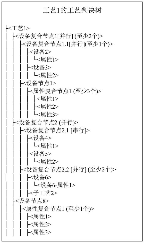
logical relationship between each device in the process to be detected; detect the state of each device in the process to be detected; according to the state of each device, and the logical relationship between each device in the process decision tree , determine the state of the process to be detected; before obtaining the process decision tree of the process to be detected, the method further includes: generating a process decision tree of the process to be detected, the process decision tree includes at least one of the following nodes: equipment Node, process node, equipment compound node, attribute node and attribute compound node, wherein, the equipment node represents a device object, the process node represents another process object referenced by the process to be detected, and the device compound node represents the Composed compound object, the attribute node represents an attribute object, and the attribute compound node represents a compound object composed of
multiple attribute objects; generating the process decision tree of the process to be detected includes: creating at least one root node of the process decision tree , and add corresponding parameters for each root node, wherein the type of the root node includes at least one of the following: equipment node, process node, and equipment compound node; the parameters of the equipment node include the equipment ID, and the parameters of the process node include the process ID, The parameters of the device compound node include the physical connection relationship and logical relationship of each child node under the device compound node; create child nodes under each root node, where the child nodes under the device node are attribute nodes or attribute compound nodes, and the child nodes under the attribute node No child nodes, the child nodes under the attribute compound node are attribute compound nodes or attribute nodes; there are no child nodes under the process node; the child nodes under the device compound node are device compound nodes, equipment nodes or process nodes; the parameters of the attribute compound node include The logical relationship of each child node under the attribute composite node, the parameters of the attribute node include the attribute identifier and the normal interval of the attribute
[0007] The embodiment of the present invention also provides a
system for detecting the state of the process, which is used to solve the problem that there is no general state detection scheme in the prior art to automatically detect complex processes. The system includes: a
data source management module for providing The equipment data of each equipment in the process to be detected; the process management module is connected with the
data source management module, and is used to determine the state of the process to be detected according to the equipment data of each device in the process to be detected based on the process decision tree of the process to be detected, Wherein, the process decision tree is used to determine the logical relationship between the various devices in the process to be detected; the process management module is also used to: before determining the state of the process to be detected: generate a process decision tree of the process to be detected, The process decision tree includes at least one of the following nodes: equipment node, process node, equipment composite node, attribute node, and attribute composite node, wherein the equipment node represents a device object, and the process node represents another node referenced by the process to be detected. A process object, the equipment composite node represents a
composite object composed of equipment objects and process objects, the attribute node represents an attribute object, and the attribute composite node represents a
composite object composed of
multiple attribute objects; wherein, the process for generating the process to be detected A decision tree, including: creating at least one root node of the process decision tree, and adding corresponding parameters to each root node, wherein the type of the root node includes at least one of the following: equipment node, process node, and equipment composite node; The parameters of the equipment node include the equipment identification, the parameters of the process node include the
process identification, and the parameters of the equipment composite node include the physical connection relationship and logical relationship of each sub-node under the equipment composite node; create sub-nodes under each root node, among which, the equipment The child nodes under the node are attribute nodes or attribute compound nodes, there are no child nodes under the attribute node, and the child nodes under the attribute compound node are attribute compound nodes or attribute nodes; there are no child nodes under the process node; Equipment composite node, equipment node or process node; the parameters of the attribute composite node include the logical relationship of each child node under the attribute composite node, and the parameters of the attribute node include attribute identification and attribute
normal range[0008] The embodiment of the present invention also provides a
computer device, which is used to solve the problem that there is no general state detection scheme in the prior art to automatically detect complex processes, including a memory, a processor, and a device stored in the memory and can be used in the processor. A
computer program running on the computer, when the processor executes the
computer program, the above-mentioned method for detecting the process state is realized


