
Wire stripping machine

A wire stripping machine and wire rod technology, which can be used in circuit/collector parts, cable installation devices, electrical components, etc., and can solve problems such as low degree of stripping automation.

Pending Publication Date: 2019-04-05
SHENZHEN HAIPENGXIN ELECTRONICS
View PDF16 Cites 19 Cited by
  • Summary
  • Abstract
  • Description
  • Claims
  • Application Information

AI Technical Summary

Problems solved by technology

[0003] The purpose of the present invention is to provide a wire stripping machine, which aims to solve the problem of low automation of stripping in the prior art

Method used


Image

  • Wire stripping machine
  • Wire stripping machine
  • Wire stripping machine

Examples


Embodiment Construction

[0030] In order to make the object, technical solution and advantages of the present invention clearer, the present invention will be further described in detail below in conjunction with the accompanying drawings and embodiments. It should be understood that the specific embodiments described here are only used to explain the present invention, not to limit the present invention.

[0031] It should be noted that when an element is referred to as being “fixed” or “disposed on” another element, it may be directly on the other element or be indirectly on the other element. When an element is referred to as being "connected to" another element, it can be directly connected to the other element or indirectly connected to the other element.

[0032]It is to be understood that the terms "length", "width", "top", "bottom", "front", "rear", "left", "right", "vertical", "horizontal", "top" , "bottom", "inner", "outer" and other indicated orientations or positional relationships are ba...


PUM


Abstract

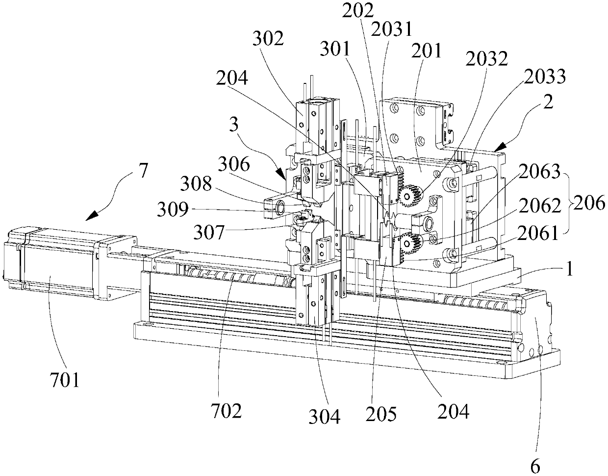
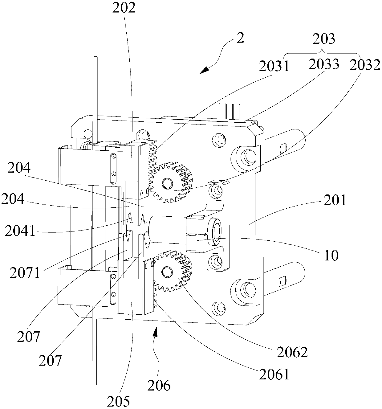
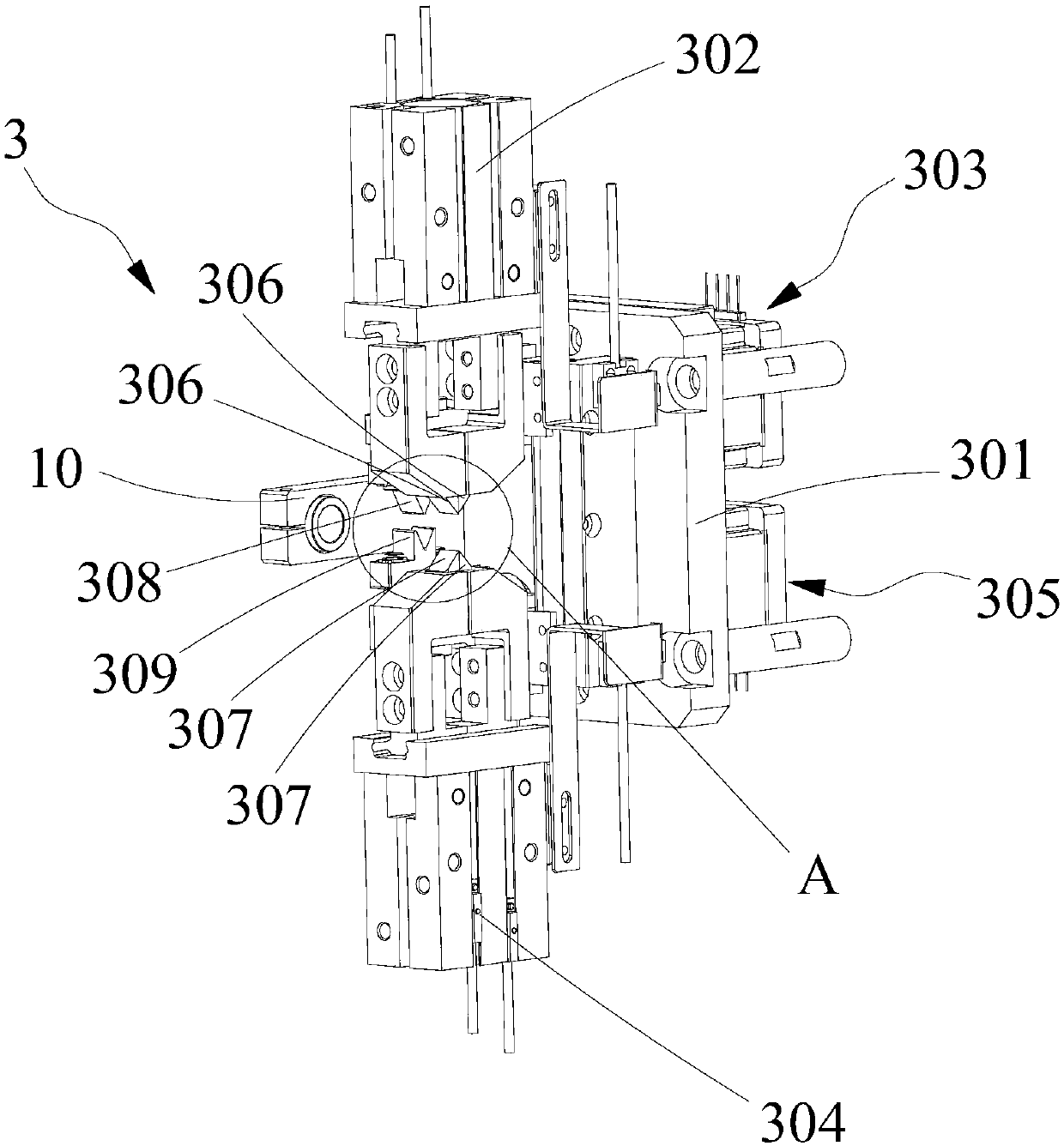
The invention discloses a wire stripping machine. The wire stripping machine comprises a bottom mounting plate, a ring cutting device and a peeling device; the ring cutting device comprises a ring cutting fixing plate, a first cutter seat, a first ring cutting driving mechanism, a second cutter seat, a second ring cutting driving mechanism, at least one first ring cutter and at least one second ring cutter; the peeling device comprises a peeling fixing plate, a first pneumatic finger, a first peeling drive mechanism, a second pneumatic finger, a second peeling drive mechanism, first peeling cutters and a second peeling cutter. The first ring cutter and the second ring cutter cooperate to cut off the skin of a certain portion of the wire, the first peeling cutter and the second peeling cutter cut into the skin, then the movable ends of the first pneumatic finger and the second pneumatic finger are opened, since the two movable ends of the first pneumatic finger are both provided with the first peeling cutters to achieve that the skin is stirred to two sides for movement to achieve peeling treatment so as to improve the automation of the peeling.

Description

technical field [0001] The invention relates to the field of wire stripping equipment, in particular to a wire stripping machine. Background technique [0002] The finished wires are usually sold as longer wires after being wound and packaged. In order to meet their own production needs, users usually need to process longer wires to meet their use needs. For example, the skin of the wire needs to be stripped. The existing wire stripping device can only circumscribe the skin, and then manually peel off the skin of the wire. After the circumcision, it is difficult to manually peel off the skin, and the degree of automation is low. Contents of the invention [0003] The object of the present invention is to provide a wire stripping machine, aiming to solve the problem of low automation of stripping in the prior art. [0004] For reaching this purpose, the present invention adopts following technical scheme: [0005] Wire stripping machine, comprising a bottom mounting plate...

Claims


Application Information

Patent Timeline
Patent Type & Authority Applications(China)
IPC IPC(8): H01R43/28H02G1/12
CPCH01R43/28H02G1/127Y02W30/82
Inventor 刘辉翔陈进谢述红陈清李叶来
Owner SHENZHEN HAIPENGXIN ELECTRONICS
Learn More