Piezoelectric microphone

A microphone and piezoelectric technology, which is applied in the field of acoustic-electric conversion, can solve the problems affecting the performance of the microphone and the deformation of the flap of the diaphragm, and achieve the effect of reducing the gap, improving the uniformity, and improving the consistency

Inactive Publication Date: 2019-04-05
AAC ACOUSTIC TECH (SHENZHEN) CO LTD
View PDF5 Cites 14 Cited by
  • Summary
  • Abstract
  • Description
  • Claims
  • Application Information

AI Technical Summary

Problems solved by technology

[0007] Aiming at the technical problem that the deformation of the flaps of the diaphragm of the piezoelectric microphone in the related art is different due to the influence of stress during the processing process, thereby affecting the performance of the microphone, the present invention provides a piezoelectric microphone with better performance. electric microphone

Method used


Image

  • Piezoelectric microphone
  • Piezoelectric microphone
  • Piezoelectric microphone

Examples


Embodiment 1

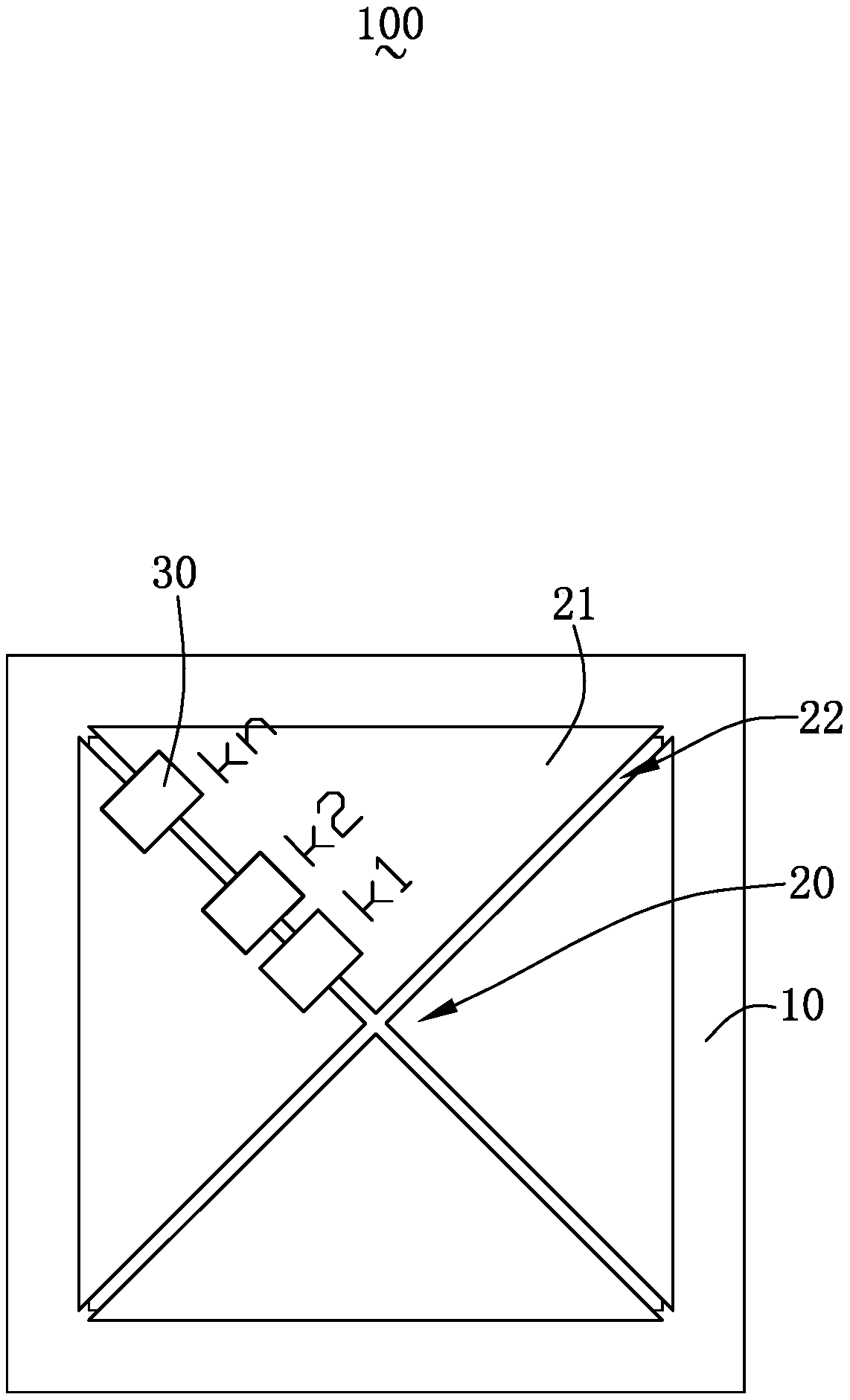
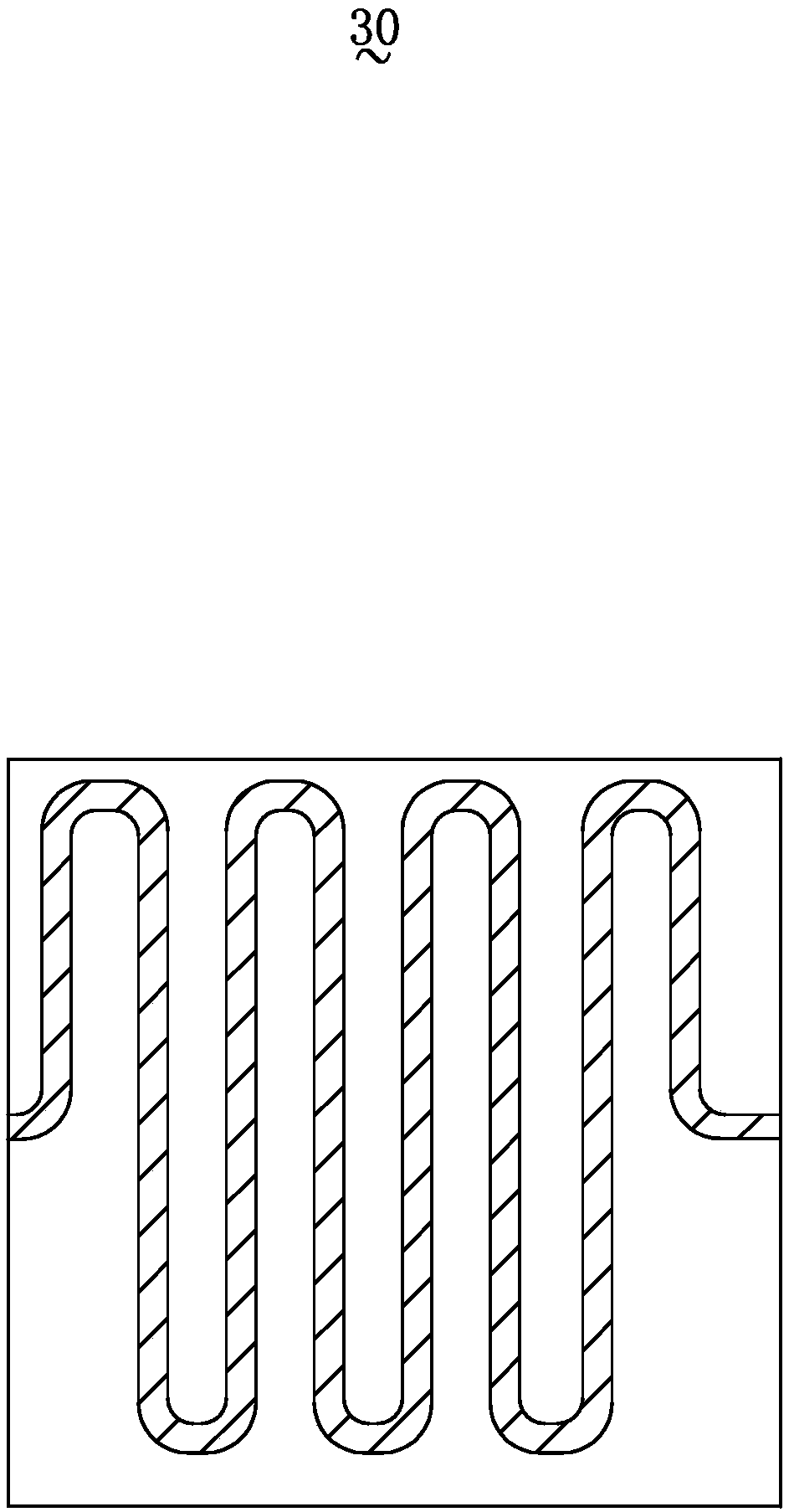
[0026] Please refer to figure 2 and image 3 . This embodiment provides a piezoelectric microphone 100, which includes a substrate 10 with a cavity back, a piezoelectric cantilever diaphragm 20 fixed on the substrate 10, and a piezoelectric cantilever diaphragm 20 fixed on the piezoelectric microphone 100. The elastic expansion part 30.

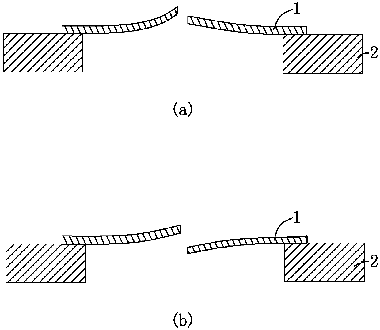
[0027] The piezoelectric cantilever beam diaphragm 20 is composed of a plurality of diaphragms 21, one end of each diaphragm 21 is fixed to the base 10, the other end is suspended above the back cavity, and each adjacent two diaphragms The flaps 21 are spaced apart to form gaps 22 .

[0028] It should be noted that, in this embodiment, four valves 21 are provided, and all four valves 21 have a triangular structure, and the four valves 21 connect the piezoelectric cantilever diaphragm 20 are surrounded by a rectangular structure. Correspondingly, four gaps 22 are correspondingly provided. Certainly, in other embodiments, the number of t...

Embodiment 2

[0040] Please refer to Figure 4 . This embodiment provides a piezoelectric microphone 200, the structure of the piezoelectric microphone 200 is basically the same as that of the piezoelectric microphone 100 in Embodiment 1, the difference lies in:

[0041]The piezoelectric cantilever diaphragm 120 of the piezoelectric microphone 200 is composed of four fan-shaped diaphragms 121 , and the four diaphragms 121 surround the piezoelectric cantilever diaphragm 120 into a circular structure. There are a plurality of elastic stretchable members 130 and they are sequentially distributed between two adjacent valves 121 in the same group.

[0042] Compared with the related art, the piezoelectric microphone of the present invention connects two adjacent valve flaps by arranging the elastic elastic member between at least one group of two adjacent valve flaps, and the elastic elastic member can The adjacent valve flaps are limited in the same plane, and the elastic stretchable member ca...


PUM


Abstract

The invention provides a piezoelectric microphone, which comprises a base with a back cavity and a piezoelectric cantilever beam diaphragm fixed on the base. The piezoelectric cantilever beam diaphragm consists of a plurality of valves, one end of each valve is fixed with the base and the other end is suspended over the back cavity, and each two adjacent valves is arranged at an interval. The piezoelectric microphone also comprises elastic telescopic pieces connecting adjacent valves, and the elastic telescopic piece is arranged between at least one group of two adjacent valves. Compared witha related technology, the piezoelectric microphone provided in the invention has better performance.

Description

【Technical field】 [0001] The invention relates to the field of acoustic-electric conversion, in particular to a piezoelectric microphone. 【Background technique】 [0002] MEMS microphones are now widely used in consumer electronics. Traditional MEMS microphones are mainly capacitive microphones, which include a base, a back plate and a diaphragm formed on the base. The diaphragm and the back plate form a capacitive system. The vibration of the sound wave will drive the diaphragm of the microphone to vibrate back and forth, thereby changing the distance between the diaphragm and the back plate and the capacitance value of the plate. By detecting the change in capacitance, the sound signal can be converted into an electrical signal. When the mobile device is in a dusty environment, particles in the air are easy to enter and get stuck between the diaphragm and the back plate of the microphone, making the diaphragm unable to move; when the mobile device is in a humid environme...

Claims


Application Information

Patent Timeline
Patent Type & Authority Applications(China)
IPC IPC(8): H04R17/02
CPCH04R17/02H04R2201/003H04R31/003H04R2231/003
Inventor 段炼张睿
Owner AAC ACOUSTIC TECH (SHENZHEN) CO LTD
Why Eureka
Try Eureka