
Device for separating microplastics from soil

A separation device and technology for microplastics, applied in the direction of plastic recycling, recycling technology, etc., can solve the problems of inability to classify and separate microplastics, insufficient separation, high cost, etc., to facilitate continuous separation work, improve separation efficiency, and improve functions sexual effect

Active Publication Date: 2019-04-09
FOSHAN UNIVERSITY
View PDF8 Cites 1 Cited by
  • Summary
  • Abstract
  • Description
  • Claims
  • Application Information

AI Technical Summary

Problems solved by technology

[0003] Because microplastics are difficult to degrade, and as the top of the food chain, human beings will accumulate a large amount of microplastics in the body under the action of enrichment. Plastics are separated to prevent microplastics from polluting the environment. At present, the main method of separation is flotation, but the general use of flotation to separate microplastics is low in efficiency, and it cannot classify and separate microplastics by size, which is inconvenient. Follow-up work, while the flotation method needs to use the corresponding saturated solution, the cost is high
[0004] In the microplastic separation method and device disclosed in the Chinese Invention Patent Application Publication No. CN106363835A, although the separation device is provided with a filter membrane, the non-sedimented layer in the water body to be separated can pass through the filter membrane, and can quickly and effectively separate rivers Microplastic particles in sediments in lakes and other water bodies are separated and extracted. However, the separation method set by the separation device can only separate microplastics in water bodies, which has the disadvantages of low applicability and insufficient separation.

Method used


Image

  • Device for separating microplastics from soil
  • Device for separating microplastics from soil
  • Device for separating microplastics from soil

Examples


Embodiment Construction

[0030] The following will clearly and completely describe the technical solutions in the embodiments of the present invention with reference to the accompanying drawings in the embodiments of the present invention. Obviously, the described embodiments are only some, not all, embodiments of the present invention.

[0031] In the description of the present invention, unless otherwise stated, the meaning of "plurality" is two or more; the terms "upper", "lower", "left", "right", "inner", "outer" , "front end", "rear end", "head", "tail", etc. indicate the orientation or positional relationship based on the orientation or positional relationship shown in the drawings, and are only for the convenience of describing the present invention and simplifying the description, rather than Nothing indicating or implying that a referenced device or element must have a particular orientation, be constructed, and operate in a particular orientation should therefore not be construed as limiting ...


PUM


Abstract

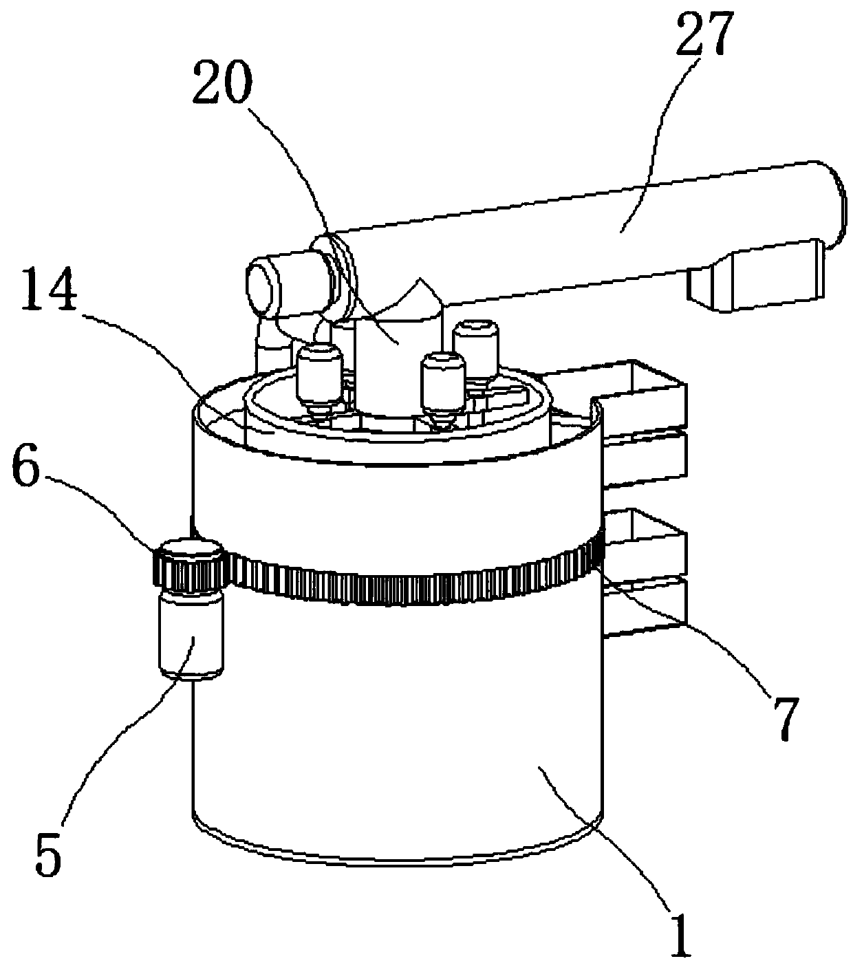
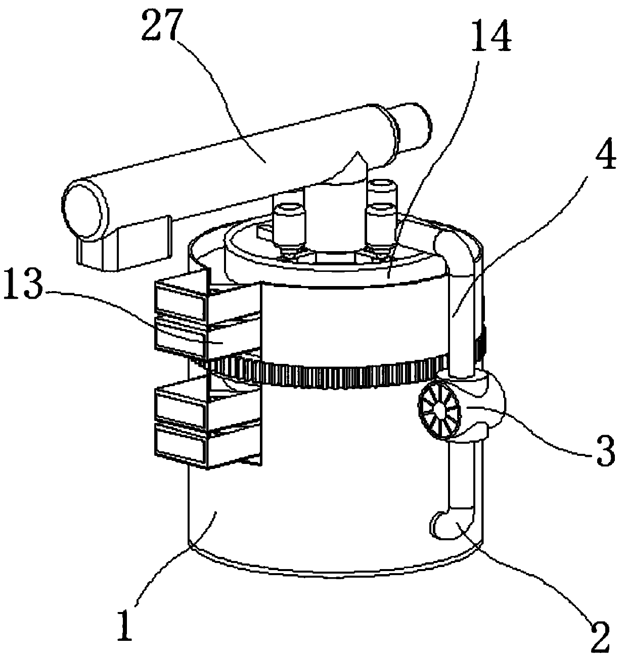
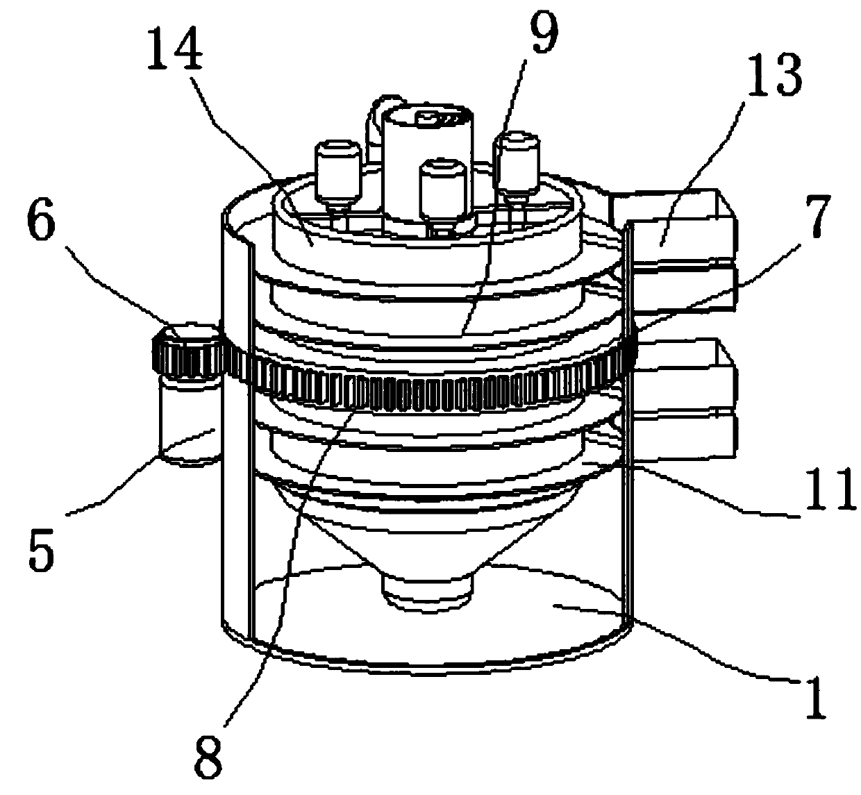
The invention discloses a device for separating microplastics from soil, and relates to the field of microplastic separation. The device specifically comprises a sealed case and a central transport tube, and the rear side of the sealed case is connected with a connecting pipe; the upper side of the connecting pipe is connected with a water pump, and a circulating water pipe is installed above thewater pump; the left side of the sealed case is provided with a motor of which the upper side is connected with a gear, and the right side of the gear is provided with a gear ring; the gear is engagedwith the gear ring, and the inner side of the gear ring is fixedly provided with a connecting ring; a rotary drum is installed at the middle of the connecting ring, and connected with the connectingring fixedly; and a clamping ring is arranged below the rotary drum. According to the device for separating the microplastics from the soil, through cooperation of the gear ring and the gear, the rotary drum of the device can be driven to rotate, thereby nesting of the rotary drum on a separation and settling pond for rotation; and thus, an annular filter plate on the outer side of the rotary drumis driven to rotate, and used for filtration and separation.

Description

technical field [0001] The invention relates to the technical field of separation of microplastics, in particular to a separation device for separating soil and microplastics in soil. Background technique [0002] Microplastics refer to plastic particles and textile fibers with very small particle sizes. Due to the widespread existence of microplastics in the marine environment and various definite and uncertain hazards to organisms, they have received widespread attention from all walks of life. Microplastics It is divided into two categories: primary microplastics and secondary microplastics. Primary microplastics refer to industrial products of plastic particles discharged into the water environment through rivers, sewage treatment plants, etc., such as microplastic particles contained in cosmetics or used as industrial raw materials Secondary microplastics are plastic particles made of large plastic waste through physical, chemical and biological processes that cause spl...

Claims


Application Information

Patent Timeline
Patent Type & Authority Applications(China)
IPC IPC(8): B29B17/02
CPCB29B17/02B29B2017/0224B29B2017/0244Y02W30/62
Inventor 吴小莲莫测辉方铮徐小亚王海龙
Owner FOSHAN UNIVERSITY
Learn More