Machining automatic feeding device and method
An automatic feeding and feeding technology, which is applied in the direction of conveyors, transportation and packaging, etc., can solve problems such as difficult to achieve intermittent transmission, and achieve the effect of good versatility and compact structure
- Summary
- Abstract
- Description
- Claims
- Application Information
AI Technical Summary
Problems solved by technology
Method used
Image
Examples
Embodiment 1
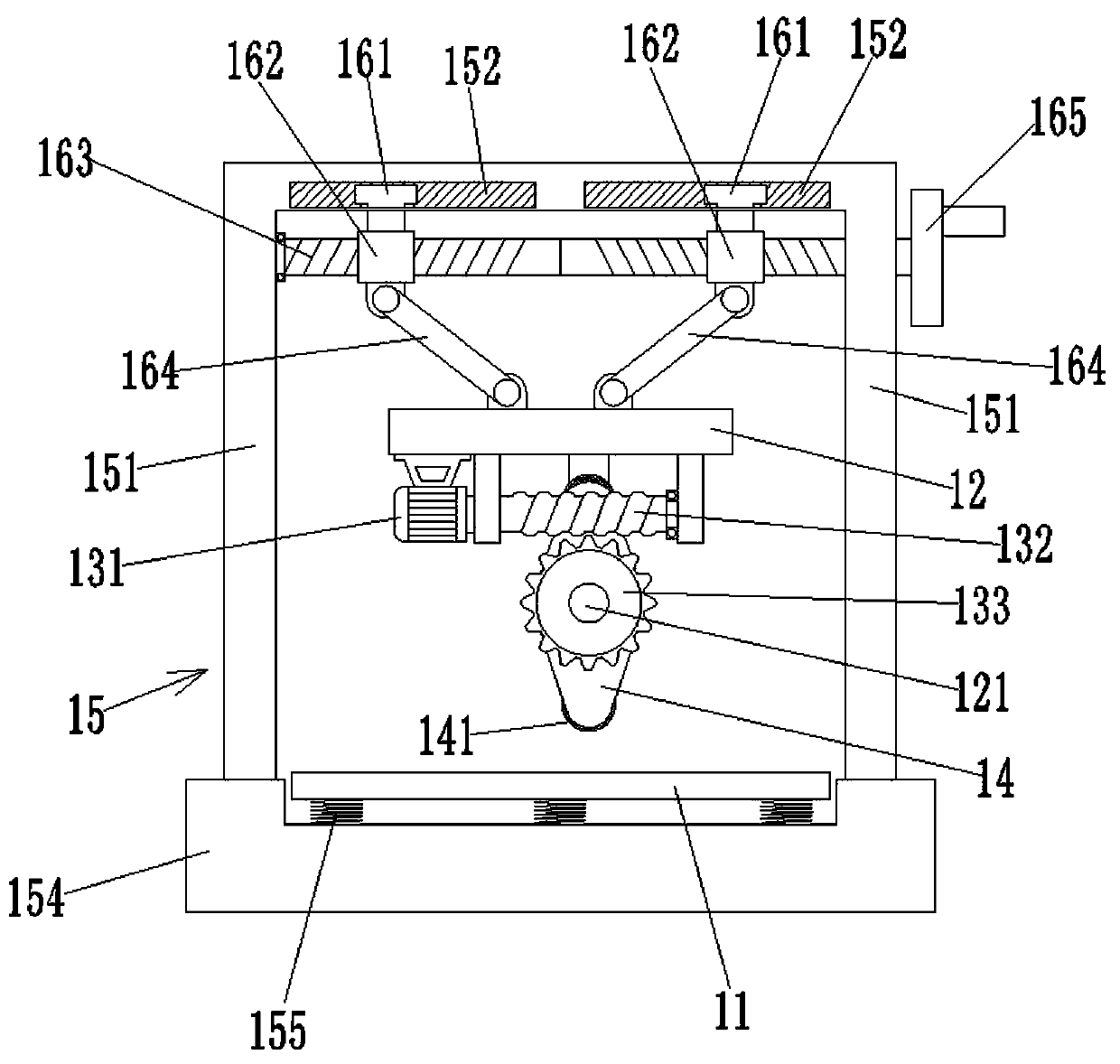
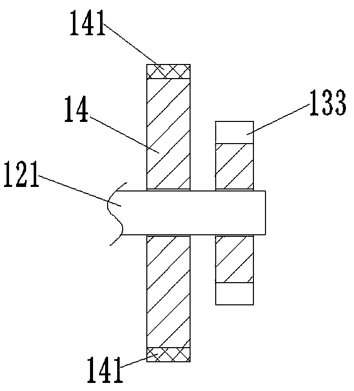
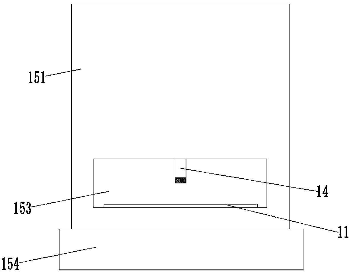
[0036] Please also refer to Figure 1 to Figure 3 .
[0037] Such as figure 1 As shown, the machine-added automatic feeding device provided by the embodiment of the present invention includes a feeding bottom plate 11 on which processed materials such as plates and bars are placed and forwarded along the feeding bottom plate 11 .
[0038] The top of the feed base 11 is provided with a mounting frame 12, and a rotating shaft 121 is arranged on the mounting frame 12. The rotating shaft 121 is freely rotatably installed on the mounting frame 12 through a bearing, and a power mechanism that drives the rotating shaft 121 to rotate is installed on the mounting frame 12. .
[0039] The power mechanism includes a motor 131 and a worm screw 132 arranged on the mounting bracket 12, and a worm gear 133 that is installed on the rotating shaft 121 and matches the worm screw 132. The output shaft of the motor 131 is connected with the worm screw 132, and the worm screw 132 is meshed with ...
Embodiment 2
[0049] see Figure 4 to Figure 6 .
[0050] Such as Figure 4 As shown, the difference between this embodiment and Embodiment 1 is that two through holes are respectively provided at both ends of the rubber layer 141, and two corresponding screw holes are respectively provided on both sides of the convex part of the cam 14, and the rubber layer 141 Be installed on the boss of cam 14 by screw 142, like this, when rubber layer 141 wears and tear after using for a long time, can replace. In addition, the distance between the screw holes on both sides of the protrusion of the cam 14 along the surface of the cam 14 is slightly greater than the distance between the through holes at both ends of the rubber layer 141 to ensure that the rubber layer 141 is tensioned on the protrusion.
[0051] Further, such as Figure 5 As shown, four strip-shaped protrusions 1411 made of rubber are provided on the lower surface of the rubber layer 141 . The lower surface of the strip-shaped protru...
Embodiment 3
[0053] see Figure 7 and Figure 8 .
[0054] The feeding method that the embodiment of the present invention provides adopts the machine-added automatic feeding device in embodiment 2, as Figure 7 As shown, it specifically includes the following steps:
[0055] S1: Adjust the cam to be at an appropriate height, place an adjusting plate on the feeding base plate that is consistent with the specification of the material plate to be conveyed, and manually turn the shaft so that the bottom end of the rubber layer on the side of the cam is pressed against the adjusting plate , Adjust the cam to move up and down through the height adjustment mechanism, so that the bottom part of the strip-shaped protrusion on the rubber layer is compressed by 2-5mm.
[0056] Such as Figure 8 As shown, the compressed height H2 of the bar-shaped protrusion 1411 on the rubber layer 141 at the lower end of the cam 14 is 2-5mm lower than the uncompressed height H1. Different material boards have ...
PUM
| Property | Measurement | Unit |
|---|---|---|
| Height | aaaaa | aaaaa |
Abstract
Description
Claims
Application Information
 - R&D
- Intellectual Property
- Life Sciences
- Materials
- Tech Scout
- Unparalleled Data Quality
- Higher Quality Content
- 60% Fewer Hallucinations
Browse by: Latest US Patents, China's latest patents, Technical Efficacy Thesaurus, Application Domain, Technology Topic, Popular Technical Reports.
© 2025 PatSnap. All rights reserved.Legal|Privacy policy|Modern Slavery Act Transparency Statement|Sitemap|About US| Contact US: help@patsnap.com


