Double-motor two-stage boosting centrifugal pump

A centrifugal pump and dual motor technology, applied in the direction of pumps, pump devices, pump components, etc., can solve the problems of water pressure loss, different sizes of pump lifting water pressure and lift, and achieve the effect of reducing the loss of water pressure

Pending Publication Date: 2019-04-09
WUXI HAIXING SHIPPING POWER CO LTD
View PDF0 Cites 0 Cited by
  • Summary
  • Abstract
  • Description
  • Claims
  • Application Information

AI Technical Summary

Problems solved by technology

[0002] A water pump is a machine that transports or pressurizes a liquid. It transmits the mechanical energy of the prime mover or other external energy to the liquid to increase the energy of the liquid. It is mainly used to transport liquids including water, oil, acid and alkali, emulsions, and suspoemulsions. Compared with liquid metal, the main difference between water pumps is that the head of the pumped water pressure is different. For the needs of the fire protection field, the water pump needs to have enough pump water head to deal with the fire extinguishing situation of high-rise buildings. In the case of limited motor power Under normal circumstances, it is the most common method to increase the water pressure by using the multi-stage pressurization structure inside the pump body, and the multi-stage booster pump is due to the defects of the liquid flow channel structure in the process of passing the pressurization chamber of each stage , will lead to multiple impacts between the fluid and the pump casing, resulting in water pressure loss, and improving the flow channel structure inside the pump body can effectively solve the problem of internal water pressure loss

Method used


Image

  • Double-motor two-stage boosting centrifugal pump

Examples


Embodiment Construction

[0012] The following will clearly and completely describe the technical solutions in the embodiments of the present invention. Obviously, the described embodiments are only some of the embodiments of the present invention, rather than all the embodiments. Based on the embodiments of the present invention, all other embodiments obtained by persons of ordinary skill in the art without making creative efforts belong to the protection scope of the present invention.

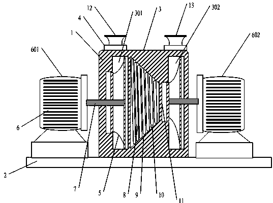
[0013] see figure 1 , the embodiment of the present invention includes:

[0014] A dual-motor two-stage booster type centrifugal pump, comprising a water pump body 1, the water pump body 1 includes a base plate 2, a water pump housing 3, a pump cover 4, a centrifugal impeller 5 and a driving motor 6, and the water pump housing 3 Fixedly installed in the middle of the upper end surface of the base plate 2, the drive motor 6 includes a primary drive motor 601 and a secondary drive motor 602, the primary drive motor 60...


PUM


Abstract

The invention discloses a double-motor two-stage boosting centrifugal pump which includes a pump body, the pump body comprises a base plate, a pump housing, pump covers, a centrifugal impeller and a driving motor, the pump housing is fixedly installed in the middle of the upper end face of the base plate, the driving motor comprises a primary driving motor and a secondary driving motor, the primary driving motor and the secondary driving motor are respectively arranged on the left and right sides of the pump housing, the inner two sides of the pump housing are respectively provided with a primary boosting bin and a secondary boosting bin. The primary boosting bin and the secondary boosting bin are vertically provided with the centrifugal impeller. An impeller drive shaft penetrates throughthe center of the centrifugal impeller, and the impeller drive shaft is derived from the left and right side walls of the pump housing. In the manner described above, the present invention enables the centrifugal pump to have a multi-stage pressurization function, and reduces pressure loss of the liquid in the conduction channel between the two-stage boosting structures.

Description

technical field [0001] The invention relates to the field of water pumps, in particular to a dual-motor, two-stage supercharging centrifugal pump. Background technique [0002] A water pump is a machine that transports or pressurizes a liquid. It transmits the mechanical energy of the prime mover or other external energy to the liquid to increase the energy of the liquid. It is mainly used to transport liquids including water, oil, acid and alkali, emulsions, and suspoemulsions. Compared with liquid metal, the main difference between water pumps is that the head of the pumped water pressure is different. For the needs of the fire protection field, the water pump needs to have enough pump water head to deal with the fire extinguishing situation of high-rise buildings. In the case of limited motor power Under normal circumstances, it is the most common method to increase the water pressure by using the multi-stage pressurization structure inside the pump body, and the multi-st...

Claims


Application Information

Patent Timeline
IPC IPC(8): F04D1/08F04D13/06F04D29/22F04D29/42F04D29/44
CPCF04D1/08F04D13/06F04D29/2222F04D29/426F04D29/445
Inventor 沈耀兴毛乔章
Owner WUXI HAIXING SHIPPING POWER CO LTD
Why Eureka
Try Eureka