Single-diaphragm low-resistance backflow preventer

A backflow preventer and low-resistance technology, applied in current collectors, hydroelectric power generation, machines/engines, etc., can solve the problems of large water head loss, inability to open the anti-backflow mode in advance, poor anti-backflow effect, etc., to reduce water pressure loss volume effect

Pending Publication Date: 2021-07-02
TONGLING XINGRONG VALVE FITTINGS CO LTD
View PDF1 Cites 0 Cited by
  • Summary
  • Abstract
  • Description
  • Claims
  • Application Information

AI Technical Summary

Problems solved by technology

[0005] First, the water head loss is relatively large, because it requires the water flow to continuously push the front check valve disc and the rear check valve disc, which greatly reduces the delivery pressure of the water flow;
[0006] Second, the anti-backflow effect is poor, because it only turns on the anti-backflow mode when backflow occurs at the rear check valve disc, and the anti-backflow mode cannot be turned on in advance;
[0007] Third, it does not have an alarm function. When backflow or insufficient water pressure occurs, it cannot prompt the operation and maintenance personnel in time

Method used


Image

  • Single-diaphragm low-resistance backflow preventer
  • Single-diaphragm low-resistance backflow preventer
  • Single-diaphragm low-resistance backflow preventer

Examples


Embodiment Construction

[0044] In order to more clearly understand the above objects, features and advantages of the present invention, the present invention will be further described below in conjunction with the accompanying drawings and embodiments. It should be noted that, in the case of no conflict, the embodiments of the present application and the features in the embodiments can be combined with each other.

[0045] In the following description, many specific details are set forth in order to fully understand the present invention. However, the present invention can also be implemented in other ways than described here. Therefore, the present invention is not limited to the specific embodiments disclosed below. limit.

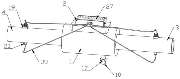
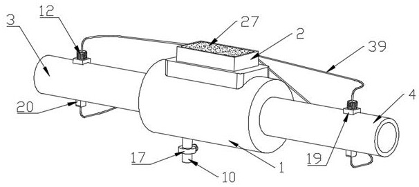
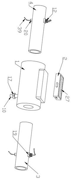
[0046] A single-diaphragm low-resistance backflow preventer of this embodiment, refer to Figure 1-14 : Including main pipe 1, drive assembly, detection assembly and control box 2.

[0047] The nozzles of the input and output ends of the main pipe 1 are respectively sealed an...


PUM


Abstract

The invention relates to the technical field of backflow preventers, in particular to a single-diaphragm low-resistance backflow preventer. The single-diaphragm low-resistance backflow preventer comprises a main pipe, a driving assembly, a detection assembly and a control box. Pipe openings in the input end and the output end of the main pipe are in sealed connection with a water inlet pipe and a water outlet pipe correspondingly, a first isolation cavity and a second isolation cavity which are separated by a coaxial annular partition plate are formed in the middle in the main pipe, the first isolation cavity is close to the water inlet pipe, the radius of the pipe openings in the two ends of the main pipe is equal to the radius of the inner ring of the annular partition plate, star-shaped supports are fixed in the first isolation cavity and the second isolation cavity correspondingly, and a water drainage pipe is further arranged at the position, located at the first isolation cavity, of a pipe body of the main pipe. The driving assembly comprises propellers, generators, coils, elastic assemblies, baffles, electromagnets and a one-way electromagnetic valve. The detection assembly comprises angle sensors and hydraulic sensors. The control box is arranged on the outer side pipe wall of the main pipe. The single-diaphragm low-resistance backflow preventer can effectively solve the problems that in the prior art, the head loss is large, the backflow prevention effect is poor, and the alarm function is not achieved.

Description

technical field [0001] The invention relates to the technical field of backflow preventers, in particular to a low-resistance backflow preventer with a single diaphragm. Background technique [0002] The backflow preventer is a fluid control device that strictly limits the pressure water in the pipeline to flow in one direction only. [0003] In the patent document with the application number: CN201921347615.6, a single diaphragm low-resistance backflow preventer is disclosed. The bottom end of the main valve body is provided with a drain channel and a drain device arranged on the drain channel. The device includes a drain joint, a drain valve seat, a drain valve disc, a guide vane nut and a drain spring, the drain joint is installed on the drain channel, and the drain valve seat is arranged on the drain channel above the drain joint Above, the drain valve disc is fixed on the bottom of the main valve stem and cooperates with the main valve stem, the drain valve disc is als...

Claims


Application Information

Patent Timeline
Patent Type & Authority Applications(China)
IPC IPC(8): F16K15/06F16K15/18F16K11/10F16K27/02F16K37/00H02J7/35F03B13/00F03B11/00
CPCF03B11/008F03B13/00F16K11/10F16K15/066F16K15/18F16K27/0209F16K27/0263F16K37/005F16K37/0058H02J7/35Y02E10/20
Inventor 徐亮亮
Owner TONGLING XINGRONG VALVE FITTINGS CO LTD
Why Eureka
Try Eureka