
Heat dissipation fin high in heat dissipation efficiency, of radiator

A technology of cooling fins and radiators, which is applied to heat exchange equipment, lighting and heating equipment, laminated components, etc. Air flow, the effect of increasing the contact area

Inactive Publication Date: 2019-04-09
SUZHOU INDAL PARK ELION TECH
View PDF7 Cites 0 Cited by
  • Summary
  • Abstract
  • Description
  • Claims
  • Application Information

AI Technical Summary

Problems solved by technology

Although this type of heat dissipation fin can be used for heat dissipation, the air intake efficiency of the heat dissipation fin is low, and the heat dissipation efficiency is low.

Method used


Image

  • Heat dissipation fin high in heat dissipation efficiency, of radiator
  • Heat dissipation fin high in heat dissipation efficiency, of radiator
  • Heat dissipation fin high in heat dissipation efficiency, of radiator

Examples


Embodiment 1

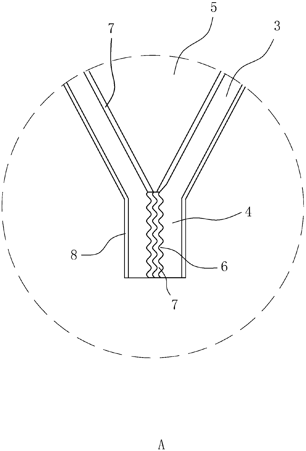
[0042] refer to figure 2 , a high-efficiency heat dissipation radiator fin, including a composite board 1 and an inner turbulent flow sheet 2, the composite board 1 is provided with two pieces, the composite board 1 is extended with drainage fins 3 on both sides, and the drainage fins 3 are facing away from There is a connecting piece 4 along the direction of the composite board 1; two composite boards 1 are symmetrically arranged, and the two composite boards 1 are connected to form a fluid channel 5, and the inner turbulent flow sheet 2 is arranged in the fluid channel 5, and the inner turbulent flow sheet 2 and the composite The plate 1 is fixedly connected; the composite plate 1, the drainage piece 3, the connecting piece 4 and the internal turbulence piece 2 are all made of 3003 aluminum alloy, the composite plate 1, the drainage piece 3 and the connecting piece 4 are integrally formed, and the aluminum alloy sheet is used to fold The 3003 aluminum alloy has better therm...

Embodiment 2

[0050] refer to Figure 4 , a high-efficiency heat dissipation radiator fin, the difference from Embodiment 1 is that the drain fin 3 is in an "S" shape, and the joints between the drain fin 3, the composite plate 1 and the connecting fin 4 are all smooth transition connections. When the vehicle is running, the airflow coming in front of the vehicle contacts the connecting piece 4 and then divides into two strands. Under the guidance of the drainage piece 3, it adheres to the drainage piece 3 and quickly flows to the composite board 1, bringing the heat on the composite board 1 to the composite board 1. Go; the guidance of the air-drain 3 reduces the rebound of the airflow, and because the air-drain 3 is streamlined, the speed of the airflow is faster, thereby improving the efficiency of air intake and heat dissipation.

Embodiment 3

[0052] refer to Figure 5 , a high-efficiency heat dissipation radiator fin, the difference from Example 1 is that: only one side of the composite board 1 is provided with a drain piece 3, and the drain piece 3 extends toward a direction away from the composite board 1 with a connecting piece 4; The composite board 1 is arranged symmetrically along the center, the connecting sheet 4 is directly bonded to the composite board 1 , and a solder layer 7 is provided on the side of the connecting sheet 4 facing the opposite composite board.


PUM


Abstract

The invention discloses a heat dissipation fin high in heat dissipation efficiency, of a radiator, is applied to the field of heat dissipation equipment, and solves the technical problems that a conventional heat dissipation fin is low in wind inlet efficiency and low in heat dissipation efficiency. The heat dissipation fin is characterized by comprising two composite boards and an internal turbulence piece, wherein drainage pieces extend along the side edges of the composite boards; connecting pieces extend facing the direction away from the composite board, of the drainage piece; a fluid channel is formed between the two composite boards; the internal turbulence piece is arranged in the fluid channel; and the two composite boards are mutually and symmetrically arranged. The heat dissipation fin disclosed by the invention has the technical effect that each connecting piece is directly connected with the corresponding opposite connecting piece or the opposite composite board; and the contact surface area of perpendicular contact between the air current and the heat dissipation fin is reduced, so that the air inlet capacity is increased, and the heat dissipation efficiency is improved.

Description

technical field [0001] The invention relates to the field of heat dissipation equipment, in particular to a radiator fin with high heat dissipation. Background technique [0002] The car radiator is generally installed on the car. The function of the car radiator is to reduce the air temperature, reduce the heat load of the engine, increase the air intake, and then increase the power of the engine. The main function of the car radiator is the cooling fin. . [0003] Currently, if figure 1 As shown, the radiating fins on the market are generally composed of a composite plate 1, a seal 9, and an inner turbulence sheet 2. When the airflow collides with the seal 9 and the composite plate 1, most of the airflow is bounced back. Although the heat dissipation fins can be used for heat dissipation, the air intake efficiency of the heat dissipation fins is low, and the heat dissipation efficiency is low. Contents of the invention [0004] The purpose of the present invention is ...

Claims


Application Information

Patent Timeline
Patent Type & Authority Applications(China)
IPC IPC(8): F28F3/06
CPCF28F3/06
Inventor 李建龙邓克权张中华
Owner SUZHOU INDAL PARK ELION TECH
Learn More