Equipment for continuously rolling metal plates and strips

A metal strip and continuous rolling technology, which is applied in metal processing equipment, metal rolling, metal rolling, etc., can solve the problems of changing stress state, reducing the service life of rolls, and low bending section coefficient, so as to reduce the contact surface Stress reduction, floor space saving, compact structure of the unit

Inactive Publication Date: 2009-11-11
秦建平
View PDF1 Cites 0 Cited by
  • Summary
  • Abstract
  • Description
  • Claims
  • Application Information

AI Technical Summary

Problems solved by technology

The disadvantages of using back-up rolls to support the work rolls are: (1) The work rolls and the back-up rolls are theoretically in line contact, the surface contact stress is large, the stress state changes at high frequency, the material is prone to fatigue damage, and the service life of the roll is reduced
(2) The line contact between the work roll and the back-up roll causes the roll to be in an unstable stress state, and horizontal support needs to be applied to it
(3) The back-up roller is bulky, has low bending section coefficient, and low effective utilization rate of materials
(4) It is difficult to manufacture the support roller and the processing cost is high
(5) The rolling mill is bulky and the stress loop is long, resulting in a reduction in the stiffness of the rolling mill
(6) Since the rolling force is transmitted to the frame by the backup roller bearing, the backup roller bearing is expensive and requires high maintenance technology

Method used


Image

  • Equipment for continuously rolling metal plates and strips

Examples


Embodiment Construction

[0015] The production process of the present invention is as follows: the billet is rolled in the rough rolling unit composed of several two-roll strip mills → rolled in the intermediate rolling unit composed of several two-roll strip mills through the roller table → rolled through the rolling mill It enters the finishing rolling unit composed of several two-roll strip mills for rolling → enters the coiler to coil the rolled parts into strip coils → collects the finished strip coils through the conveying system and puts them into storage.

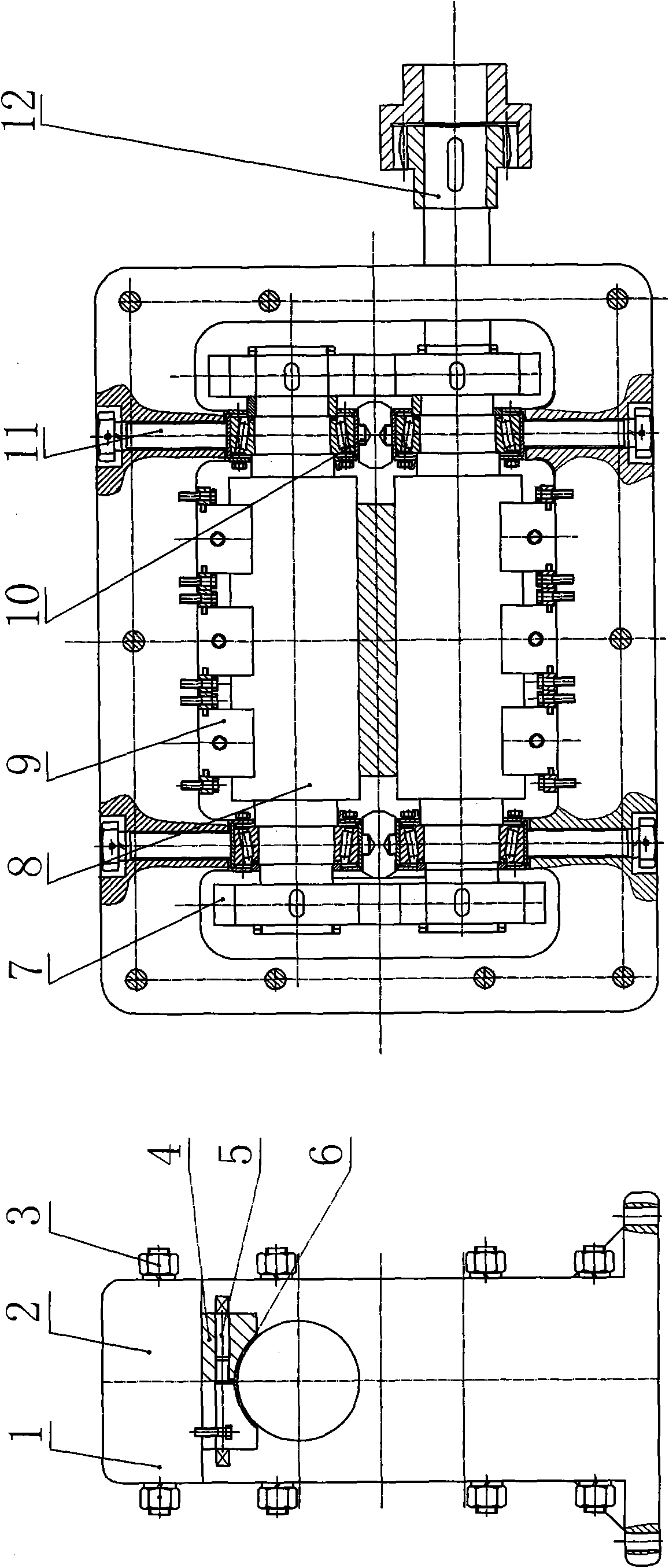
[0016] The structure of the two-roll strip mill is a frame formed by connecting the left frame 1 and the right frame 2 through connecting bolts 3. The shape of the frame is rectangular when viewed along the rolling direction. On the parts corresponding to the roller device 8 on the upper and lower sides, there are depressing screws 11 for adjusting the distance between the rollers. The deflection of the two rollers is adjusted through the su...


PUM


Abstract

The invention discloses equipment for continuously rolling metal plates and strips, which belongs to the technical field of the continuous rolling of metal plates and strips and is applicable to the continuous rolling production line of metal plates and strips. The equipment is characterized in that a rough rolling unit, a middle rolling unit and a fine rolling unit in the production line respectively consist of a base, and a motor, a speed reducer gearbox, a gear distribution box and a plurality of double-roller plate and strip rolling machines thereon; the inlet and the outlet of each rolling machine are respectively provided with a guiding and guarding device. The equipment is also characterized in that a left frame and a right frame are closed by stop bolts to form the frame of the double-roller plate and strip rolling machine; the shape of the flame is rectangular when seen along the rolling direction; housing screws, which are used for regulating the spacing between the rollers, are arranged in corresponding positions both on the upper surface and lower surface of the frame; the double-roller plate and strip rolling machine adopts surface contact roller supporting systems arranged in sections; the surface contact roller supporting systems of the double-roller plate and strip rolling machine are arranged between the frame and the internal rollers of the frame; each surface contact roller supporting system consists of two supporting blocks; the contact surfaces of the supporting blocks and the rollers are coated with an antifriction material; a technical lubricating system continuously supplies the surfaces of the supporting blocks with a lubricant; and a regulating device is used for regulating the contact pressure between the supporting blocks and the rollers so as to change the deflection of the rollers.

Description

technical field [0001] The invention belongs to the technical field of rolling metal plates and strips, and in particular relates to equipment used in a continuous rolling production line for rolling metal plates and strips. Background technique [0002] At present, there are two ways to roll metal sheets and strips. One is the reversible rolling of ordinary strip mills. Roll it over again, and repeat the rolling until the finished product is rolled out; the other is continuous rolling with multiple ordinary strip rolling mills arranged in series, and the rolled pieces pass through each rolling mill one by one, and the thickness is continuously reduced until the finished product is rolled. Roll out the finished product. The equipment used in these two rolling methods are ordinary strip rolling mills. Since the strip rolling requires a small roll diameter, the roll needs to be supported in order to meet the strength and rigidity requirements of the roll. Ordinary strip mill...

Claims


Application Information

Patent Timeline
Patent Type & Authority Applications(China)
IPC IPC(8): B21B1/24B21B31/02B21B29/00
Inventor 张素颖秦建平郭拉凤秦川刘玲玲
Owner 秦建平
Why Eureka
Try Eureka