Tunnel piston effect mitigation device

A technology of piston effect and tunnel, which is applied in tunnel systems, mining equipment, roads, etc., and can solve problems such as easy generation of high-voltage waves

Active Publication Date: 2021-10-29
浙江同浙土木工程技术有限公司
View PDF5 Cites 0 Cited by
  • Summary
  • Abstract
  • Description
  • Claims
  • Application Information

AI Technical Summary

Problems solved by technology

[0003] The present invention intends to provide a tunnel piston effect mitigation device to solve the problem that high-voltage waves are easily generated when high-speed rail enters the tunnel

Method used


Image

  • Tunnel piston effect mitigation device
  • Tunnel piston effect mitigation device
  • Tunnel piston effect mitigation device

Examples


Embodiment

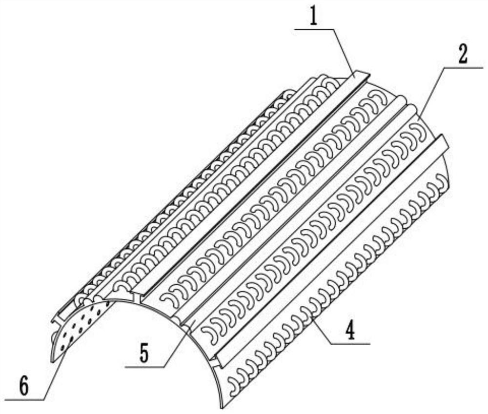
[0023] This embodiment is basically as figure 1 , figure 2 Shown:

[0024] Tunnel piston effect mitigation device, mounting components, several high-pressure wave absorbing components and several exhaust components.

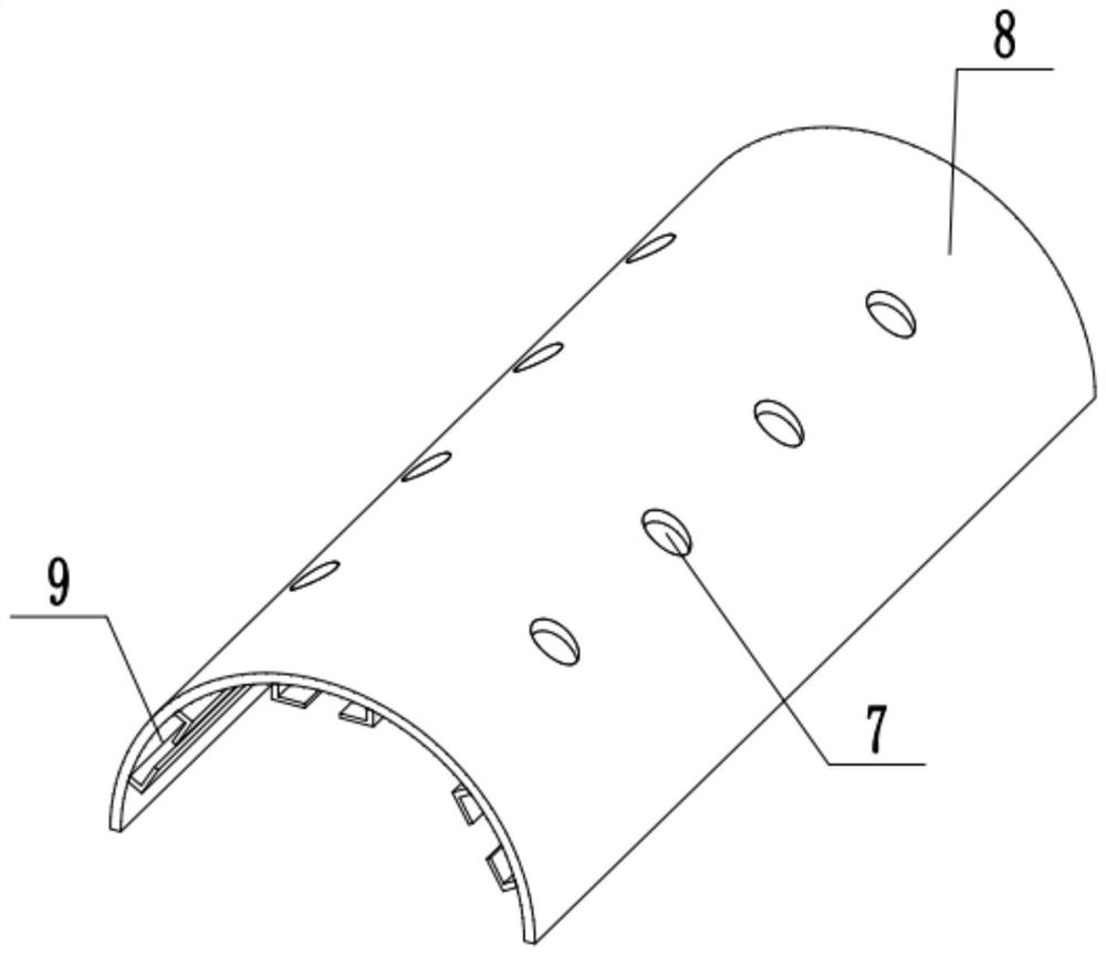
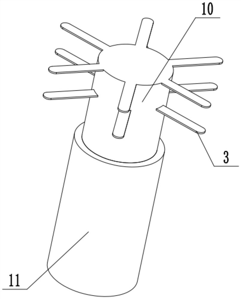
[0025] combine figure 2 , image 3 , according to the distance of the tunnel, select an appropriate number of embedded parts, before pouring the tunnel, wrap the connecting plate 3 on the embedded rod 10 on the structural steel bars of the reinforced tunnel to complete the fixing of the embedded parts, and then use concrete Pouring the prefabricated parts of the tunnel, and then installing the prefabricated parts on the inner wall of the newly opened tunnel. After the construction of the entire tunnel is completed, select the isolation cover 8 with a suitable length, and set up a number of positions corresponding to the number of embedded parts on the isolation cover 8. The connection holes 7 are then connected together with the connection sleeve 11 of the ...


PUM


Abstract

The invention relates to the field of tunnel engineering, and specifically discloses a tunnel piston effect mitigation device, including a mounting assembly, several high-pressure wave absorbing assemblies, and several exhaust assemblies. The curved functional cover inside, the arc of the isolation cover is consistent with the inner wall of the tunnel and the outer surface of the isolation cover is attached to the inner wall of the tunnel, the arc of the functional cover is consistent with the inner surface of the isolation cover and the outer surface of the functional cover is attached to the inner surface of the isolation cover. The high-pressure wave absorbing assembly includes several piston tubes and several pistons. The piston tubes are connected and installed on the functional cover. The end of the piston tube facing the inside of the functional cover is an air inlet. At least one piston is slidably arranged in each piston tube. The exhaust assembly includes an exhaust pipe, and the exhaust pipes are installed on the functional cover. The side of the exhaust pipe facing the inside of the functional cover is evenly distributed with a number of air inlets. This invention solves the problem that high-pressure waves are easily generated when the high-speed rail enters the tunnel. .

Description

technical field [0001] The invention relates to the field of tunnel engineering, and specifically discloses a tunnel piston effect mitigation device. Background technique [0002] Piston Effect (Piston Effect) refers to the train running at high speed in the tunnel, which will drive the air in the tunnel to generate high-speed flow, because it is similar to the phenomenon that the piston in the cylinder compresses the gas. When a high-speed train enters the tunnel, the air in the tunnel is still. Due to the impact of the train, a high-pressure wave is generated. The high-pressure wave propagates at the speed of sound (much greater than the speed of the train). The tunnel top wall bounces back on the high-speed rail and causes the high-speed rail to vibrate. As the speed of the high-speed rail is getting faster and faster, for example, the country is developing a high-speed rail with a speed of 600km / h. Such vibration may cause the high-speed rail to derail. , providing a tu...

Claims


Application Information

Patent Timeline
Patent Type & Authority Patents(China)
IPC IPC(8): B61B13/10E21F17/00
CPCB61B13/10E21F17/00
Inventor 陈雪英
Owner 浙江同浙土木工程技术有限公司
Why Eureka
Try Eureka