Circular groove skeleton type optical cable

A skeleton optical cable and circular groove technology, which is applied in the field of optical cables, can solve the problems of increased friction and extrusion of optical fibers, small space in rectangular grooves of skeleton cables, and loss, etc., to increase the number of loads, reduce fiber loss, and improve accommodation volume effect

Inactive Publication Date: 2019-04-09
SHENZHEN SDG INFORMATION CO LTD
View PDF7 Cites 10 Cited by
  • Summary
  • Abstract
  • Description
  • Claims
  • Application Information

AI Technical Summary

Problems solved by technology

In the inherent rectangular groove, the optical fiber ribbon is laid flat on the bottom of the groove when no force is applied. When entering the groove, it will be affected by various forces, so that the originally regular rectangular optical fiber ribbon will be forced into an irregular quadrilateral, which will greatly increase the probability of the optical fibers at the four vertices of the optical fiber ribbon being rubbed and squeezed, resulting in loss greater than the theoretical value
[0004] 1. When the bottom edge of the rectangular groove of the skeleton cable is at right angles, the optical fiber ribbon is deformed and turned over in the groove, and it is easy to squeeze the optical fibers at the four corners of the optical fiber ribbon stack to cause loss
[0005] 2. The space of the rectangular slot of the skeleton cable is small, the movement of the optical fiber in the slot is limited, and it is easy to generate friction with the inner wall when receiving tensile stress and lateral compressive stress, causing loss
[0006] 3. The rectangular groove of the skeleton cable will squeeze the outermost optical fiber ribbon when the sheath is squeezed out of the water blocking belt, causing loss
[0007] 4. The number of optical fiber ribbons carried by the rectangular groove is limited, and the number cannot be increased

Method used


Image

  • Circular groove skeleton type optical cable
  • Circular groove skeleton type optical cable

Examples


Embodiment Construction

[0020] It should be understood that the specific embodiments described here are only used to explain the present invention, not to limit the present invention.

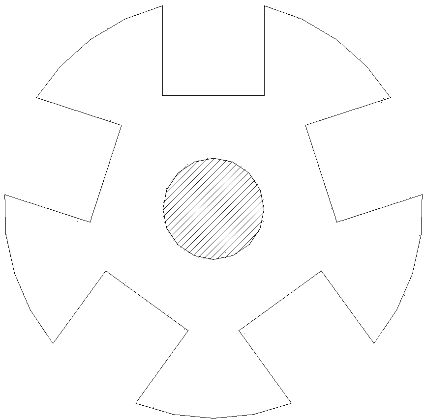
[0021] Considering that the skeleton groove of the current skeleton optical cable generally adopts a rectangular groove or a U-shaped groove, the optical fiber ribbon in it is easy to damage the optical fiber when it is subjected to extrusion, side bending, friction, tensile stress and compressive stress, thereby causing loss. Therefore, the present invention provides a circular groove skeleton type optical cable.

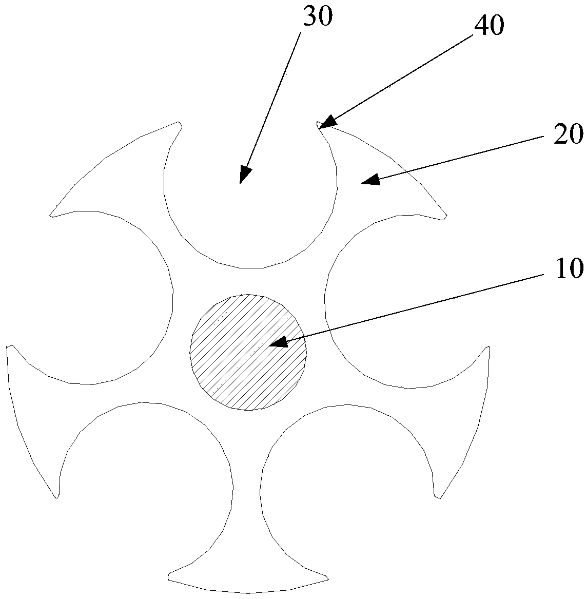
[0022] Please refer to figure 2 , figure 2 It is a structural schematic diagram of a preferred embodiment of the circular groove skeleton optical cable of the present invention.

[0023] Such as figure 2 As shown, the circular groove skeleton type optical cable proposed in this embodiment includes a strengthening member 10 and a skeleton 20 arranged on the outer periphery of the strengthening member ...


PUM


Abstract

The invention relates to a circular groove skeleton type optical cable. The circular groove skeleton type optical cable comprises a reinforce, and a skeleton arranged at the periphery of the reinforce; a cross section of the skeleton is circular shaped, a plurality of skeleton slots for placing the optical fiber ribbons are uniformly formed on an outer wall of the skeleton, and the cross section of each skeleton slot is semi-circular. The defect that the loss is caused since the optical fiber is damaged when the optical fiber ribbons are subject to extrusion, side-bending, friction, tensile stress and pressure stress in the prior art is overcome, the bearing amount of the optical fiber ribbon by the skeleton slot is effectively increased, the carrying capacity is improved, the cost performance of the optical cable with large number of cores is higher, and the optical fiber loss is reduced.

Description

technical field [0001] The invention relates to the technical field of optical cables, in particular to a circular groove skeleton optical cable. Background technique [0002] With the rapid development of optical fiber communication business and the sharp increase of information demand, the traditional small-core optical cable has been difficult to meet the needs of actual communication. In particular, due to the limitation of underground pipeline resources, an optical cable with a small outer diameter and a large number of cores is urgently needed in the market. Skeleton optical fiber ribbon cable has attracted attention due to its high optical fiber density, convenient construction and installation, and many other advantages. Skeleton optical cable is made by stacking the prepared optical fiber ribbons in the spiral skeleton groove to make the cable core, wrapping the skeleton with water blocking tape, and then adding protective material (PE material) to the cable core t...

Claims


Application Information

Patent Timeline
Patent Type & Authority Applications(China)
IPC IPC(8): G02B6/44
CPCG02B6/443G02B6/4432
Inventor 陈焕新刘涛王晓锋王新龙周旻浩王辅东
Owner SHENZHEN SDG INFORMATION CO LTD
Why Eureka
Try Eureka