A tunnel under-excavation detection method based on image three-dimensional reconstruction and a grid curved surface

A 3D curved surface and 3D reconstruction technology, applied in image analysis, image data processing, details involving processing steps, etc., can solve problems such as expensive equipment, high environmental quality requirements, and complicated operations

Pending Publication Date: 2019-04-09
CENT SOUTH UNIV
View PDF2 Cites 15 Cited by
  • Summary
  • Abstract
  • Description
  • Claims
  • Application Information

AI Technical Summary

Problems solved by technology

[0004] In order to solve the technical defects of the over-under-break detection method in the prior art, such as low efficiency, low precision, expensive equipment, complicated operation, and high r

Method used


Image

  • A tunnel under-excavation detection method based on image three-dimensional reconstruction and a grid curved surface
  • A tunnel under-excavation detection method based on image three-dimensional reconstruction and a grid curved surface
  • A tunnel under-excavation detection method based on image three-dimensional reconstruction and a grid curved surface

Examples


Embodiment 1

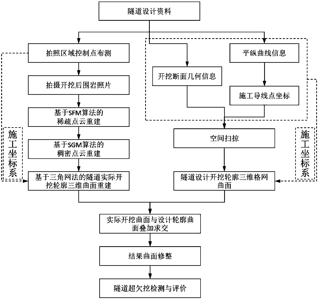
[0126] see figure 1 , the present invention provides a tunnel overbreak and underbreak detection method based on image three-dimensional reconstruction and grid surface, see figure 1 , including the following steps:

[0127] S1: Arrange the control points in the actual excavation surrounding rock image acquisition area of ​​the tunnel.

[0128] First, make a calibration plate with high contrast, which can clearly identify the center position. Then arrange the calibration boards on the actual excavation contour face of the tunnel and the left and right walls, generally 3-5 calibration boards are advisable. Finally, the total station is used to assist in the measurement, and the real-world space coordinates of the center of the calibration plate are obtained as the measurement control point. The working face is the face on which the excavation tunnel (in coal mining, mining or tunneling) is continuously advanced.

[0129] S2: Obtain the surrounding rock image after tunnel exca...

Embodiment 2

[0158] A project MHTJ-30 standard single-hole single-track heavy-duty railway tunnel, the starting and ending mileage is DK1660+177.00~DK1668+349.00, the total length of the tunnel is 8172m, and the maximum buried depth is 266.46m. The section selected in the example is DK1663+454.3926~DK1663+457.4781, and the section form of the excavation section is IV c type section, the central axis of the tunnel is in a straight line segment.

[0159] Arrangement of control points in the image acquisition area of ​​the actual excavation outline of the tunnel: the actual excavation outline face and the left and right side walls of the section DK1663+454.3926~DK1663+457.4781. The coordinates of the center of the calibration plate.

[0160] According to the rules and methods of photo collection, 36 photos were collected per linear meter along the actual excavation contour of the tunnel along the central axis of the tunnel, and 90 photos were uniformly collected on the face of the tunnel, an...


PUM


Abstract

The invention discloses a tunnel ultra-under-excavation detection method based on image three-dimensional reconstruction and a grid curved surface, and belongs to the field of tunnel engineering. Thetunnel real excavation contour curved surface is obtained through photo three-dimensional reconstruction, the tunnel real excavation contour curved surface is compared with the gridded tunnel design excavation contour curved surface, the tunnel ultra-under-excavation detection condition is obtained, the tunnel ultra-under-excavation amount, the ultra-under-excavation area and the size can be detected, and a basis is provided for evaluation of ultra-under-excavation. The method has the advantages of low detection equipment cost, no construction interference, comprehensive detection range and visual and accurate detection result.

Description

technical field [0001] The invention relates to the field of tunnel engineering, in particular to a tunnel overbreak and underbreak detection method based on image three-dimensional reconstruction and grid surface. Background technique [0002] During tunnel construction, the phenomenon of over- and under-excavation is common. Over and under excavation not only affects the safety of tunnel construction and the stability of surrounding rock, but also directly affects the quality and cost of engineering construction. Therefore, accurate detection of overbreak and underbreak is particularly important. Accurate and comprehensive test results can reflect the quality of tunnel excavation and blasting control, and can also provide a basis for cost calculations such as increasing excavation and support. [0003] At present, traditional methods such as total stations are commonly used in engineering to detect tunnel overbreak and underbreak. Through on-site practice, it is found th...

Claims


Application Information

Patent Timeline
IPC IPC(8): G06T7/00G06T17/05G06T17/20
CPCG06T7/0004G06T17/05G06T17/20G06T2200/08
Inventor 祝志恒阳军生张宇傅金阳王维富张志明张聪王立川张学民黄定著
Owner CENT SOUTH UNIV
Why Eureka
Try Eureka