Pipeline protection structure of road construction, and mounting method thereof

A technology for pipeline protection and road construction, which is applied in the direction of cable installation, cable installation in ground conduits, and cable installation devices. It can solve problems such as pipeline damage, reduce pipeline damage, save labor, and avoid wear and tear.

Active Publication Date: 2019-04-09
温州金德市政建设有限公司
View PDF7 Cites 7 Cited by
  • Summary
  • Abstract
  • Description
  • Claims
  • Application Information

AI Technical Summary

Problems solved by technology

Therefore, when the vehicle is running, the wheels will crush the p

Method used


Image

  • Pipeline protection structure of road construction, and mounting method thereof
  • Pipeline protection structure of road construction, and mounting method thereof
  • Pipeline protection structure of road construction, and mounting method thereof

Examples


Embodiment 1

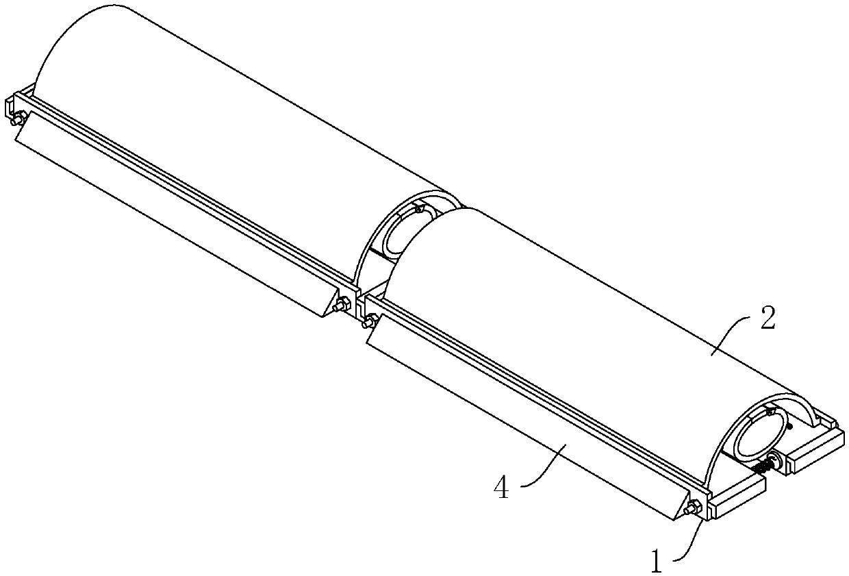
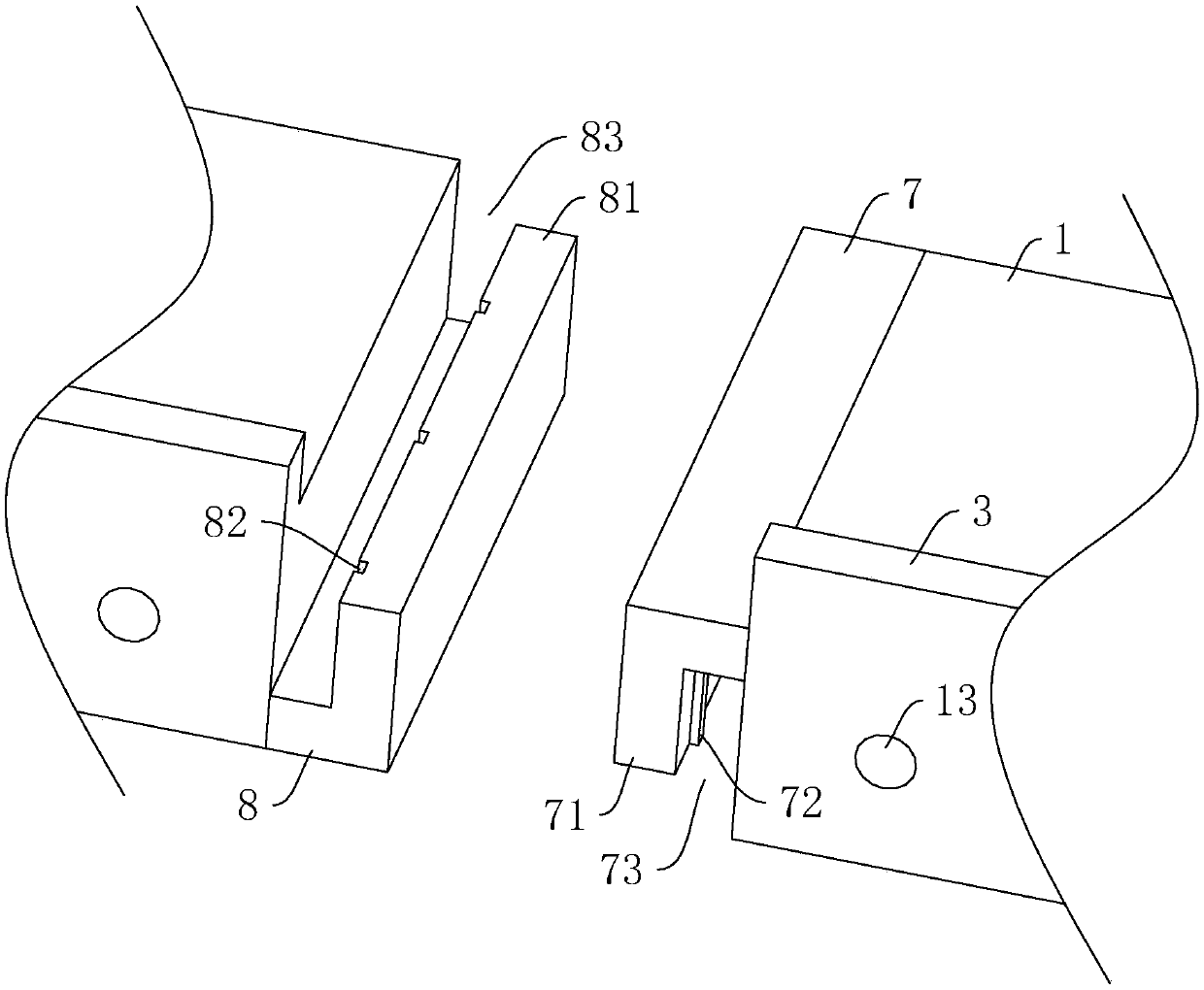
[0044] Embodiment 1: as figure 1 , figure 2 As shown, a pipeline protection structure for road construction includes a pair of bases 1 and a support plate 2 arranged on the pair of bases 1 . Support blocks 3 are vertically provided on the upper end surfaces of the sides of the base 1 facing away from each other, and inclined slopes 4 are provided on the outer side walls of the base 1 .

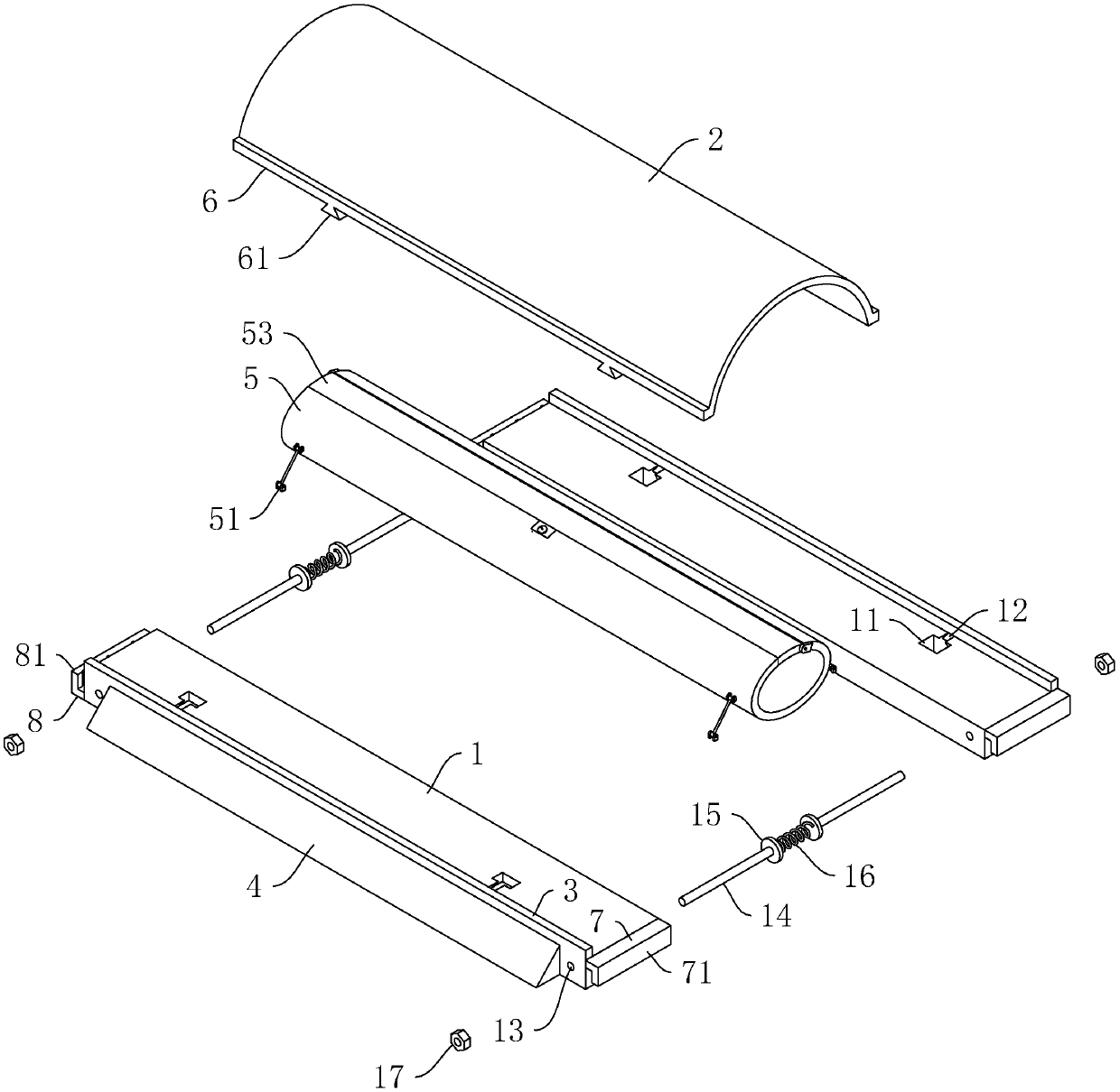
[0045] Such as figure 2 As shown, the structure also includes a protective cover 5 , a pair of pull rods 51 are hinged to the sidewall of the lower end of the protective cover 5 , and the lower ends of the pair of pull rods 51 are respectively hinged to the upper end surfaces of the pair of bases 1 .

[0046] Such as figure 2 As shown, the support plate 2 is in an arch shape, and both ends of the support plate 2 are provided with mounting blocks 6 . Both ends of the lower end surface of the mounting block 6 are provided with a dovetail block 61, and the upper end surface of the base 1 i...

Embodiment 2

[0066] Embodiment 2: An installation method for installing the above-mentioned pipeline protection structure, comprising the following steps:

[0067] S1, put a pair of bases 1 flat on the road, and make the sides with slopes 4 away from each other;

[0068] S2, splicing multiple sets of bases 1 according to the width of the road surface;

[0069] S3, place the limit rod 14 between the pair of bases 1, and then insert the ends of the pair of limit rods 14 away from each other into the limit holes 13 on the pair of bases 1;

[0070] S4, the pipeline is installed inside the protective cover 5;

[0071]S5, placing the mounting plate on the base 1, and inserting the dovetail block 61 on the lower end surface of the mounting block 6 into the dovetail groove 12 on the base 1;

[0072] S6, pushing a pair of bases 1 close to each other, at this time, the dovetail block 61 slides along the inner wall of the dovetail groove 12;

[0073] S7, until the inner side wall of the base 1 col...


PUM


Abstract

The invention discloses a pipeline protection structure of road construction, and a mounting method thereof. The structure comprises a pair of bases, and arched support plates arranged on the bases; mounting blocks are arranged at two ends of each support plate, support blocks propped against sidewalls of the mounting blocks are arranged on upper end surfaces of mutually departed sides of the bases; limiting holes penetrate sidewalls of two ends of the pair of bases, and limiting rods are inserted into the limiting holes in a slippage manner; base plates propped against the bases are arrangedat mutually close ends of the limiting rods, and an extension spring is arranged between a pair of base plates; two ends of each limiting rod are in threaded connection with nuts for pressing the outer sidewalls of the bases; the structure further comprises protective jacket, a pair of pull rods are hinged on the sidewall of the protective jacket, and the lower end of the pair of pull rods are hinged to upper end surfaces of the pair of bases. The pipeline protection structure disclosed by the invention comprises the advantage that the pipeline can be prevented from being damaged by arrangingthe support plates and the protective jacket to protect the pipeline; the protective jacket and the pipeline are supported by the pull rods, thereby preventing the pipeline from being soaked and corroded by the rainwater, and the pipeline damage is reduced.

Description

technical field [0001] The invention relates to the field of road construction, in particular to a pipeline protection structure for road construction and an installation method thereof. Background technique [0002] During the construction of traditional municipal roads, it is often necessary to use a variety of electrical construction equipment to carry out construction work on various positions of the road. Since it works outdoors, it is necessary to connect one end of the pipeline to the indoor power supply, and then place the other end at the construction location for use by construction equipment. [0003] However, when the construction distance is relatively long and the construction location is located on the opposite side of the road, it is necessary to lay the pipeline flat on the road surface for use by construction equipment after the pipeline crosses the road surface. Therefore, when the vehicle is running, the wheels will crush the pipeline, causing damage to ...

Claims


Application Information

Patent Timeline
IPC IPC(8): H02G9/02H02G9/04H02G1/00H02G1/08
CPCH02G1/00H02G1/08H02G9/02H02G9/025H02G9/04
Inventor 黄启盛黄立兴周思思章少央翁传恳
Owner 温州金德市政建设有限公司
Why Eureka
Try Eureka