
High-freezing-point medium gas-liquid separator with labyrinth-type gas inlet pipe heat-preserving device

A technology of gas-liquid separator and high freezing point, which is applied in separation methods, dispersed particle separation, chemical instruments and methods, etc. It can solve problems such as adhesion, blockage of pipes and equipment interiors, easy freezing and solidification, etc., to achieve enhanced heat transfer, The effect of increasing flow rate and enhancing fluidity

Active Publication Date: 2019-04-12
EAST CHINA ENG SCI & TECH
View PDF5 Cites 3 Cited by
  • Summary
  • Abstract
  • Description
  • Claims
  • Application Information

AI Technical Summary

Problems solved by technology

[0003] The present invention solves the above problems, provides a high-freezing-point medium gas-liquid separator with a labyrinth-type inlet pipe heat preservation device, and uses the labyrinth-type inlet pipe heat preservation device to optimize the high-freezing point medium gas-liquid separator to solve the traditional gas-liquid separator gas-liquid separator. It is easy to freeze and solidify, sticking, clogging pipes and problems inside the equipment

Method used


Image

  • High-freezing-point medium gas-liquid separator with labyrinth-type gas inlet pipe heat-preserving device
  • High-freezing-point medium gas-liquid separator with labyrinth-type gas inlet pipe heat-preserving device
  • High-freezing-point medium gas-liquid separator with labyrinth-type gas inlet pipe heat-preserving device

Examples


Embodiment Construction

[0029] In order to make the object, technical solution and advantages of the present invention clearer, the present invention will be further described in detail below in conjunction with the accompanying drawings and embodiments. It should be understood that the specific embodiments described here are only used to explain the present invention, and are not intended to limit the present invention.

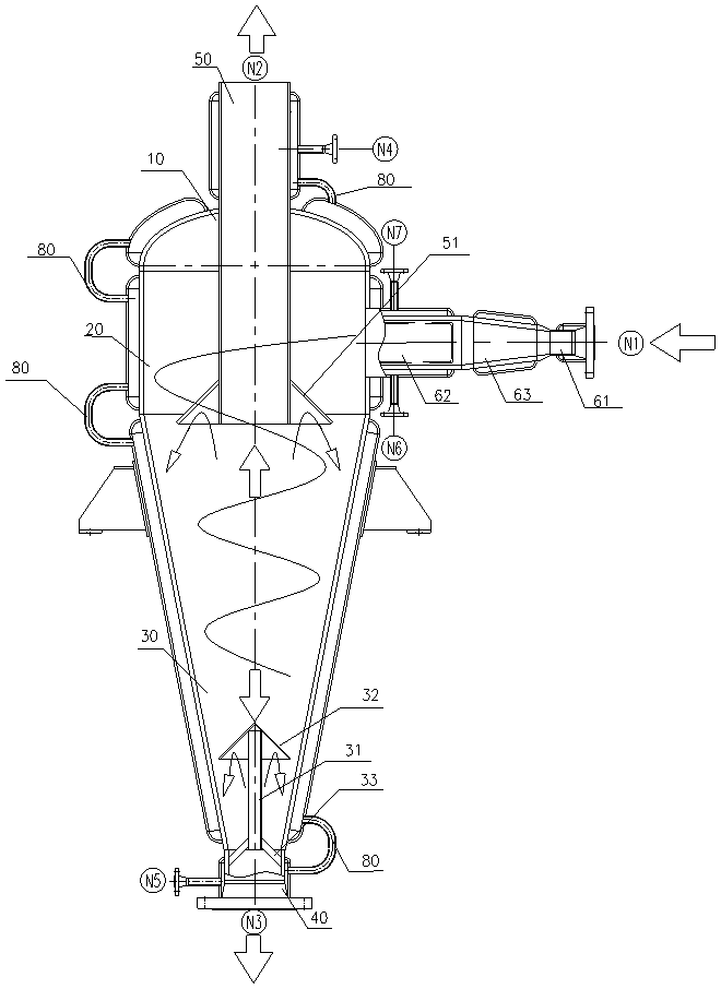
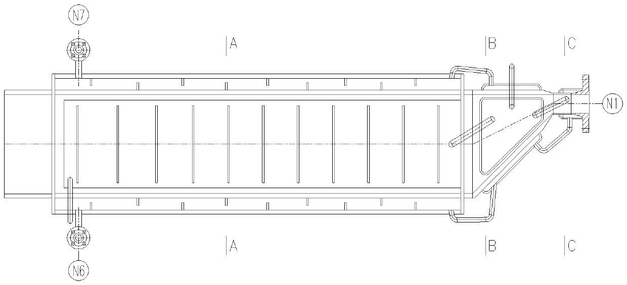
[0030]A gas-liquid separator for high freezing point medium with a labyrinth-type inlet pipe heat preservation device, which includes an elliptical head 10, a cyclone cylinder 20 and a cyclone cone 30 from top to bottom, and the top of the elliptical head 10 is provided with an exhaust pipe 50, the lower end of the exhaust pipe 50 extends into the cyclone cylinder 20, the upper end of the exhaust pipe 50 is the separation gas outlet N2, and the lower part of the exhaust pipe 50 is provided with an umbrella-shaped outlet baffle 51, the outlet baffle The diameter of the circular port...


PUM


Abstract

The invention relates to the technical field of gas-liquid separation devices in chemical engineering equipment, specifically to a high-freezing-point medium gas-liquid separator with a labyrinth-typegas inlet pipe heat-preserving device. The high-freezing-point medium gas-liquid separator successively comprises an elliptical seal head, a cyclone drum body and a cyclone cone body from top to bottom, wherein the elliptical seal head, the cyclone drum body, the cyclone cone body, a liquid discharging pipe and an exhaust pipe located at the exterior of the elliptical seal head are respectively sleeved by a heat-preserving sleeve to form heat-preserving cavities; a connecting circular pipe is arranged between adjacent heat-preserving cavities; a tangential gas inlet pipeline is arranged at one side of the drum body of the cyclone drum body and comprises a gas inlet circular pipe, a cone pipe and a rectangular pipe; four side surfaces of the cone pipe are respectively provided with a conepipe heat-preserving chamber; and four side surfaces of the rectangular pipe are respectively provided with a rectangular pipe heat-preserving chamber. According to the invention, heat-conductive oilenters from the heat-conductive oil inlet of a gas inlet pipe, respectively passes through the heat-preserving chambers located on four side surfaces of the cone pipe, the circular pipe heat-preserving chamber and the heat-preserving chambers located on four side surfaces of the rectangular pipe, and finally flows out from the heat-conductive oil outlet of the gas inlet pipe.

Description

technical field [0001] The invention relates to the technical field of gas-liquid separation equipment in chemical plants, in particular to a high-freezing-point medium gas-liquid separator with a labyrinth-type intake pipe heat preservation device. Background technique [0002] At present, there are generally gas-liquid separation equipment in chemical plants. The gas-liquid mixture enters the equipment through the tangential inlet pipe, and the separation of gas and liquid is achieved through the cyclone centrifugal force formed inside the equipment. However, at present, the gas-liquid separation equipment mainly has the problem that the medium with high freezing point is easy to freeze during the intake process, and sticks and blocks inside the equipment and the intake pipe, resulting in the failure of the equipment function. Therefore, the medium with high freezing point needs to be fed in the gas-liquid separation Before preheating, preheating generally uses special hea...

Claims


Application Information

Patent Timeline
Patent Type & Authority Applications(China)
IPC IPC(8): B01D45/16
CPCB01D45/16
Inventor 周岳琦石怀兵孟陈周
Owner EAST CHINA ENG SCI & TECH
Learn More