Vibrating-type screening device of chemical raw materials

A technology for chemical raw materials and screening devices, which is applied in the fields of sieves, chemical instruments and methods, solid separation, etc. Improve operating efficiency and improve the effect of adsorption

Active Publication Date: 2019-04-12
江西绿川生物科技实业有限公司
View PDF7 Cites 10 Cited by
  • Summary
  • Abstract
  • Description
  • Claims
  • Application Information

AI Technical Summary

Problems solved by technology

[0003] In the prior art, the screening efficiency of most screening devices is relatively low, and many powder materials are easy to block the mesh of the filter screen during the screening process, so that the screening is easily affected by blockage during long-term use. efficiency

Method used


Image

  • Vibrating-type screening device of chemical raw materials
  • Vibrating-type screening device of chemical raw materials
  • Vibrating-type screening device of chemical raw materials

Examples


Embodiment 1

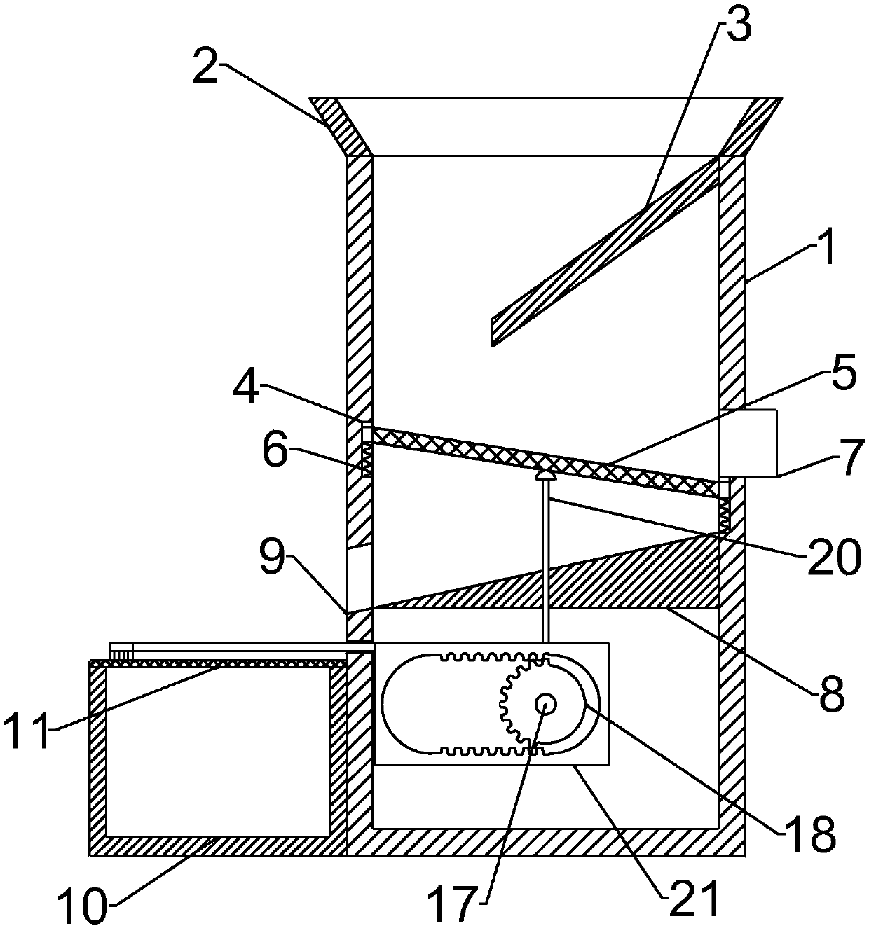
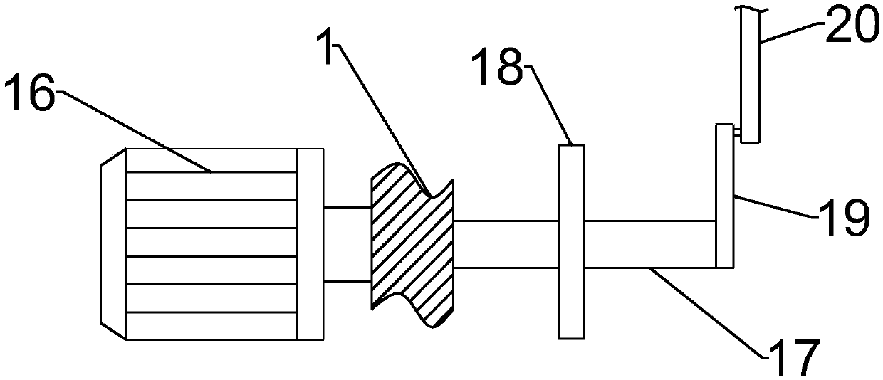
[0017] See Figure 1~2 In the embodiment of the present invention, a vibratory screening device for chemical raw materials includes a screening cavity 1, a first filter plate 5, a collecting chamber 10, a second filter plate 11, a motor 16, a rotating shaft 17 and an impact A rod 20, the two sides of the screening cavity 1 are embedded with installation grooves 4, a first filter plate 5 is connected between the installation grooves 4, and the lower end of the first filter plate 5 and the installation groove 4 There is a support spring 6 connected between the inner bottom, the left side of the screening cavity 1 is riveted with a collecting chamber 10, the upper end of the collecting chamber 10 is riveted with a second filter plate 11, the output end of the motor 16 is connected through The shaft is connected to the rotating shaft 17 for transmission, the end of the rotating shaft 17 is connected with an impact rod 20 through a connecting rod 19, and an incomplete gear 18 is wel...

Embodiment 2

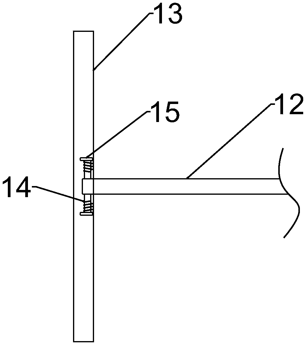
[0021] See image 3 In an embodiment of the present invention, a vibrating screening device for chemical raw materials, on the basis of embodiment 1, the sliding rod 12 is symmetrically welded with rotating pins 14 on both sides of the end, and the brush rod 13 has two upper and middle parts. A mounting plate 15 is provided for side-symmetric welding. The end of the rotating pin 14 is respectively connected to the mounting plate 15 on both sides in rotation, and a torsion spring is connected between the rotating pin 14 and the mounting plate 15.

[0022] The working principle of the present invention is: when in use, the motor 16 is started to drive the rotating shaft 17 to rotate, and the rotating shaft 17 drives the impact rod 20 to perform vertical reciprocating motion through the connecting rod 19, and the impact rod 20 continuously impacts the first filter screen during the vertical reciprocating motion. The lower end of the plate 5 makes the first filter plate 5 vibrate cont...


PUM


Abstract

The invention discloses a vibrating-type screening device of chemical raw materials. The vibrating-type screening device comprises a screening cavity, a first filter net plate, a collecting cavity, asecond filter net plate, a motor, a rotating shaft and an impact rod; mounting grooves are embedded in the two sides of the screening cavity, and the first filter net plate is connected between the mounting grooves; the output end of the motor is in connection transmission with the rotating shaft through a coupling, and the tail end of the rotating shaft is connected with the impact rod through aconnecting rod; an incomplete gear is welded to the periphery of the rotating shaft, and the periphery of the incomplete gear is connected with a swinging frame; and a sliding rod is welded to the left end of the swinging frame and movably penetrates through the left wall of the screening cavity, and the tail end of the sliding rod is connected with a brush rod. The impact rod continuously makes contact with the first filter net plate to enable the first filter net plate to shake, thus the screening efficiency is improved, the brush rod is in attachment contact with the second filter net platein a horizontal reciprocating mode, thus the passing efficiency of the second filter net plate is improved, and blockage is effectively avoided.

Description

Technical field [0001] The invention relates to the field of screening of chemical raw materials, in particular to a vibration type screening device for chemical raw materials. Background technique [0002] Chemical products need to use a variety of raw materials in the process of processing and production. Some raw materials cannot be used directly during processing. Sometimes the size of the raw materials needs to be considered, and sometimes because the raw materials are rough, they are mixed with large diameters during processing. Impurities, so the raw materials need to be screened before use. [0003] In the prior art, the screening efficiency of most screening devices is relatively low, and many powders are easy to block the mesh of the filter during the screening process, so that when used for a long time, it is easy to affect the screening due to blockage. effectiveness. Summary of the invention [0004] The purpose of the present invention is to provide a vibrating scree...

Claims


Application Information

Patent Timeline
Patent Type & Authority Applications(China)
IPC IPC(8): B07B1/34B07B1/04B07B1/42B07B1/52B07B1/46B07B9/00
CPCB07B1/04B07B1/343B07B1/42B07B1/46B07B1/4609B07B1/522B07B9/00
Inventor 吴斌
Owner 江西绿川生物科技实业有限公司
Why Eureka
Try Eureka