Shaping mold and method of thin-wall sheet metal parts

A forming method and technology of forming molds, applied in the field of sheet metal forming, can solve the problems that the size of the part cannot be guaranteed, cannot meet the use requirements, and the movement resistance of the guide rail increases, so as to save the percussion process, reduce labor intensity, Guaranteed effect of profile size

Active Publication Date: 2019-04-12
CHINA HANGFA GUIZHOU LIYANG AVIATION POWER CO LTD
View PDF15 Cites 2 Cited by
  • Summary
  • Abstract
  • Description
  • Claims
  • Application Information

AI Technical Summary

Problems solved by technology

During the processing of the part, the part is separated from the mold by tapping from one end (see the schematic diagram of the bonding of the part and the mold figure 2 ), due to the close contact between the four sides of the part and the mold, the surface size of the part cannot be guaranteed, which increases the movement resistance of the guide rail and cannot meet the use requirements

Method used


Image

  • Shaping mold and method of thin-wall sheet metal parts
  • Shaping mold and method of thin-wall sheet metal parts
  • Shaping mold and method of thin-wall sheet metal parts

Examples


Embodiment Construction

[0029] The technical scheme of the present invention will be further described below in conjunction with the accompanying drawings, but the required protection scope is not limited to the description;

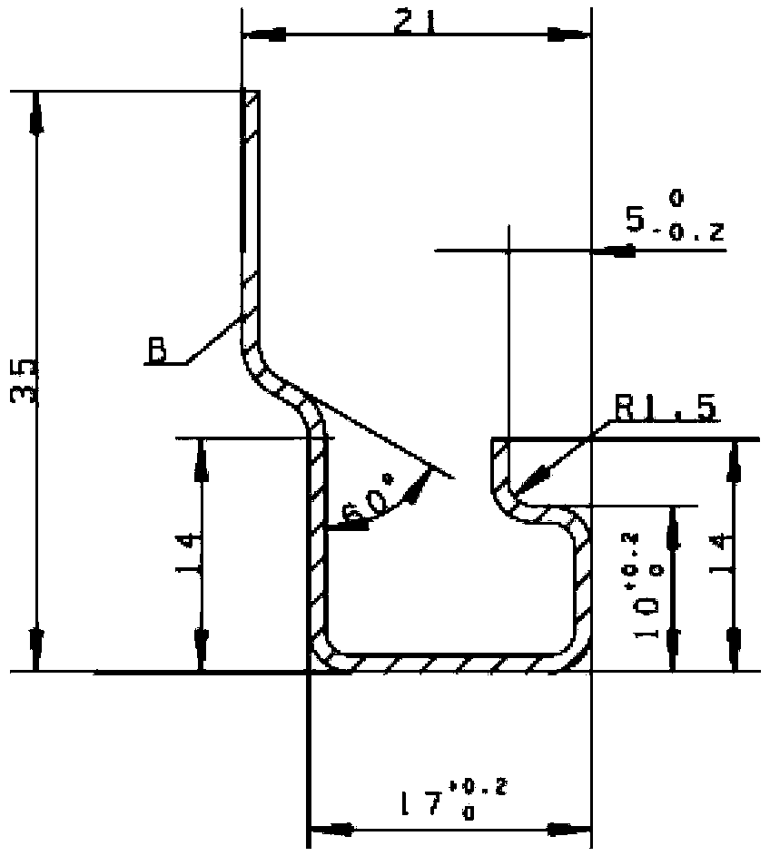
[0030] Such as figure 1 with Figure 7 Shown is the final size drawing of the parts processed by the present invention and the schematic diagram of the position of each bending section.

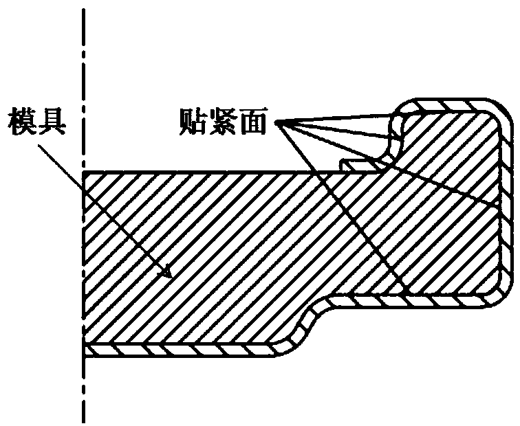
[0031] Such as figure 2 Shown is the schematic diagram of the existing processing method and mold.

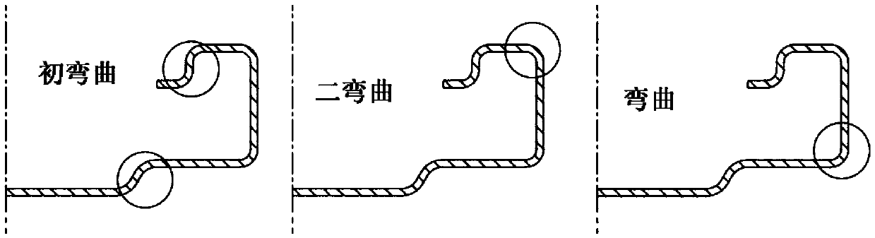
[0032] Such as image 3 As shown, it is a schematic diagram of the position corresponding to each bending in the three bendings of the present invention.

[0033] Such as Figure 4 As shown, the lower surface of the male mold of the first bending mold includes two sections of S-shaped curved surfaces, corresponding to the first S-shaped curved section 1 and the second S-shaped curved section 4, respectively, and the two sections of S-shaped curved surfaces and the outer sides are respecti...


PUM

PropertyMeasurementUnit
lengthaaaaaaaaaa

Abstract

The invention discloses a shaping mold and method of thin-wall sheet metal parts. The mold consists of three sets of sub molds including a first bending mold, a second bending mold and a third bendingmold (wherein each set of sub mold consists of a female mold and a male mold). When spare parts are processed, the three sets of sub molds are bent according to the sequence of the mold 1, the mold 2and the mold 3, and the bending positions are shown as the figure 3. The specific processing technology of the spare parts comprises the steps of performing blanking, performing bending for the firsttime,...performing bending for the second time,...and performing bending. The mold disclosed by the invention is simple to operate, the profile size of the spare parts can be guaranteed, the labor intensity of workers can be reduced, and the production efficiency of the spare parts can be improved.

Description

technical field [0001] The invention belongs to the field of mechanical processing, and in particular relates to sheet metal forming of a "ji"-shaped thin-walled part. Background technique [0002] "Ji"-shaped guide rail groove (for the structural diagram of the parts, see figure 1 ) The material is 0Cr17Ni7Al, the material thickness is t1.0, and the length of the groove of the part is L=618.5 +0.5 mm. At present, the molding process used for this type of parts is: after two extrusion and bending moldings, the parts are separated from the molding die; blanking-initial bending...-bending-...-knocking repair-correction. During the processing of the part, the part is separated from the mold by tapping from one end (see the schematic diagram of the bonding of the part and the mold figure 2 ), due to the close contact between the four sides of the part and the mold, the surface size of the part cannot be guaranteed, which increases the movement resistance of the guide rail an...

Claims


Application Information

Patent Timeline
Patent Type & Authority Applications(China)
IPC IPC(8): B21D5/00B21D37/10B23K26/00B23K26/38
CPCB21D5/00B21D37/10B23K26/0093B23K26/38
Inventor 武国栋文金龙申静芳李立新刘兴红方志忠黄顺殷炳开邱树彬井启芳张顺
Owner CHINA HANGFA GUIZHOU LIYANG AVIATION POWER CO LTD
Why Eureka
Try Eureka