Adjustable pipeline mounting, welding, assembling and moving emplacement device

A welding assembly and pipeline installation technology, which is applied in the direction of auxiliary equipment, welding equipment, auxiliary welding equipment, etc., can solve the problems of incapable pipeline assembly, single function, and inability to improve the efficiency of pipeline processing and installation, and achieve compact structure and improved work efficiency. efficiency effect

Active Publication Date: 2019-04-12
南京康达焊接设备有限公司
14 Cites 4 Cited by

AI-Extracted Technical Summary

Problems solved by technology

[0002] In the process of pipeline installation and construction, the pipeline needs to be assembled and welded. In the process of pipeline installation, some auxiliary tools are needed for auxiliary installation and construction. The existing auxiliary tools are rigid in structure and single in function, which is not convenient for pipelin...

Method used

Wherein, a side of described workbench 4 is equipped with control panel 5, is convenient to fixed cutting and welding.
Wherein, the bottom equidistant of described mobile base 3 is fixedly connected with some universal wheels 30, is convenient to move.
[0026] Wherein, the clamping ...

Abstract

The invention discloses an adjustable pipeline mounting, welding, assembling and moving emplacement device which comprises a mounting mechanism and a welding mechanism, wherein the mounting mechanismis composed of a mobile base, a work bench, a control panel, a support column, a cutting knife, a cross beam, a mobile motor, a mobile lead screw, a mobile sliding block, an angle disc, a limiting hole, an angle pin, a limiting bolt, a lifting chute, a lifting cylinder, a fixed sliding table, a clamping cylinder, a clamping clip and a limiting clip. The device is compact in structure, by arrangingthe angle disc and the lifting chute, adjustment of included angles of two pipelines is facilitated in the pipeline mounting process, the pipeline with different included angles can be assembled, andby arranging a driving gear and an outer gear ring, the pipeline is welded under the effect of a welding head, and the pipeline is cut under the effect of the cutting knife, the work efficiency of the pipeline processing and mounting is improved, and the integration of mounting, welding, assembling and moving of the pipeline is realized.

Application Domain

Welding/cutting auxillary devicesAuxillary welding devices +2

Technology Topic

EngineeringFixed Slide

Image

  • Adjustable pipeline mounting, welding, assembling and moving emplacement device
  • Adjustable pipeline mounting, welding, assembling and moving emplacement device
  • Adjustable pipeline mounting, welding, assembling and moving emplacement device

Examples

  • Experimental program(1)

Example Embodiment

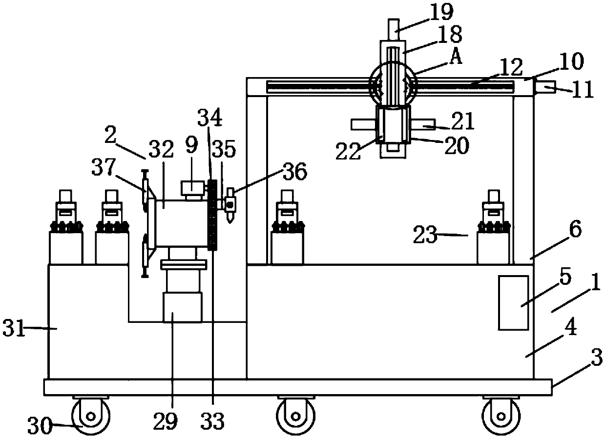
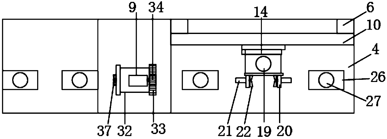
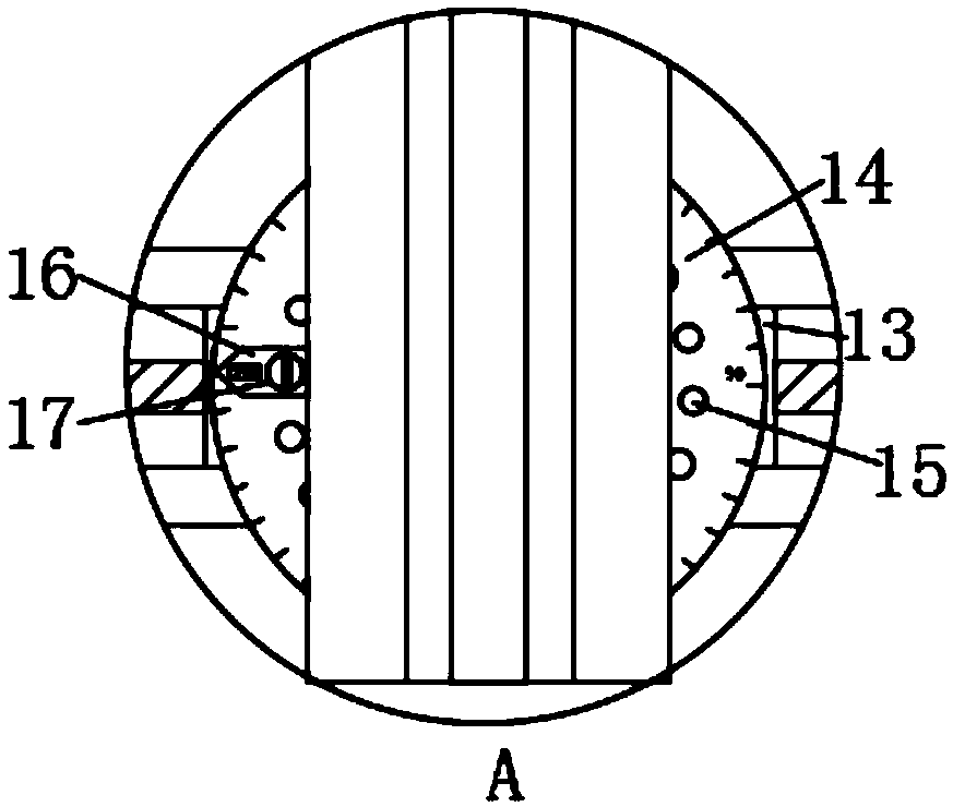
[0023] Example: such as Figure 1-6 As shown, an adjustable pipeline installation and welding assembly moving in place device of the present invention includes an installation mechanism 1 and a welding mechanism 2. The installation mechanism 1 consists of a movable base 3, a workbench 4, a control panel 5, a support column 6, and a cutting mechanism. Knife 7, beam 10, moving motor 11, moving screw 12, moving slider 13, angle plate 14, limit hole 15, angle pin 16, limit pin 17, lifting chute 18, lifting cylinder 19, fixed sliding table 20. The clamping cylinder 21, the clamping fixture 22 and the limit fixture 23 are composed of a worktable 4 fixedly connected to one end of the top of the mobile base 3, and support columns 6 are fixedly connected to both ends of the top of the worktable 4, A crossbeam 10 is fixedly connected between the tops of the two support columns 6, one end of the crossbeam 10 is fixedly connected with a moving motor 11, and the inside of the crossbeam 10 is rotatably connected with a moving screw 12, and the output of the moving motor The end is fixedly connected to one end of the moving screw, the inside of the beam 10 is slidably connected with a moving slider 13, which is threadedly connected to the moving screw 12, and the outside of the moving slider 13 is fixedly connected with an angle Disk 14, the outer side of the angle disk 14 is equidistantly excavated with a number of limit holes 15, the outer side of the angle disk 14 is rotatably connected with a lifting chute 18, the top of the lifting chute 18 is fixedly connected with a lifting cylinder 19, An angle pin 16 is fixedly connected to one side of the lifting chute 18.
[0024] Wherein, the angle pin 16 is connected to the limit hole 15 through the limit pin 17, the inside of the lifting chute 18 is slidably connected with a fixed sliding table 20, and the output end of the lifting cylinder 19 is fixedly connected to the fixed sliding table 20 , Both sides of the fixed sliding table 20 are fixedly connected with a clamping cylinder 21, the output end of the clamping cylinder 21 is fixedly connected with a clamping fixture 22, the welding mechanism 2 is composed of a rotating tube 26 and an adjusting cylinder 29 , The supporting table 31, the fixed sleeve 32, the outer gear 33, the driving gear 34, the fixed chuck 35, the electric welding head 36 and the fixed sliding sleeve 37, the top of the movable base 3 is fixedly connected with the support The table 31, the end of the support table 31 close to the workbench 4 is fixedly connected with an adjusting cylinder 29, the output end of the adjusting cylinder 29 is fixedly connected with a fixed sleeve 32, and the inside of the fixed sleeve 32 is rotatably connected with a rotary The rotating tube 26 is slidably connected to the fixed sleeve 32. The end of the rotating tube 26 close to the worktable 4 is fixedly connected with an outer ring gear 33, and the top of the fixed sleeve 32 is fixedly connected with an active motor 9.
[0025] Wherein, the output end of the driving motor 9 is fixedly connected with a driving gear 34, the driving gear 34 is in meshing connection with the outer ring gear 33, and the end of the outer ring gear 33 close to the worktable 4 is connected with electric welding through a fixing chuck 35 Head 36, the end of the rotating tube 26 away from the driving gear 34 is fixedly connected with two fixed sliding sleeves 37 symmetrically with respect to the axis. The inside of the fixed sliding sleeve 37 is slidably connected with the cutting knife 7, and the fixed sliding sleeve 37 is far away The rotating tube 26 is threadedly connected with an adjusting screw 8 in the direction of the center of the circle. The bottom of the adjusting screw 8 is rotatably connected with the cutting knife 7, and the top of the working table 4 and the top of the supporting table 31 are both fixedly connected with a limit clamp 23, The limit clamp 23 is composed of a fixed table 24, a limit roller 25, a fixed cylinder 27 and a fixed pressure plate 28. The top of the fixed table 24 is fixedly connected with a fixed cylinder 27, and the output end of the fixed cylinder 27 penetrates the fixed table. The top of 24 is fixedly connected with a fixed pressing plate 28, and both ends of the top of the fixed platform 24 are fixedly connected with four limit rollers 25.
[0026] Wherein, the clamping fixture 22 is slidably connected to the fixed sliding table 20 to facilitate clamping of the pipe.
[0027] Wherein, a control panel 5 is installed on one side of the worktable 4, which is convenient for fixed cutting and welding.
[0028] Wherein, the outer side of the angle plate 14 is equidistantly provided with scale lines to facilitate the adjustment of the angle of the lifting chute 18.
[0029] Wherein, a number of universal wheels 30 are fixedly connected to the bottom of the mobile base 3 at equal intervals for easy movement.
[0030] Wherein, the moving motor 11 and the active motor 9 are electrically connected to the control panel 5, which is convenient for welding and position adjustment.
[0031] Specifically, when the present invention is used, when metal pipes need to be welded, one of the pipes is fixed above the fixed platform 24 on the top of the workbench 4 through the fixed cylinder 27 and the fixed pressure plate 28, and then the other pipe The fixed cylinder 27 and the fixed pressing plate 28 are fixedly connected above the fixed platform 24 on the top of the support platform 31, and the interface of the two pipes is located directly under the electric welding head 36, and then the pipes of the electric welding head 36 are brought into contact with each other through the control panel 5 Control the rotation of the active motor 9. The active motor 9 drives the outer ring gear 33 to rotate through the drive gear 34, thereby driving the electric welding head 36 to move around the pipe circularly to achieve welding. When the plastic needs to be cut, the plastic pipe is fixed The cylinder 27 and the fixed pressing plate 28 are fixedly connected above the fixed table 24 on the top of the supporting table 31, and then the distance between the two cutting knives 7 is adjusted by adjusting the screw rod 8 to press the plastic pipe, and the control panel 5 controls the active The motor 9 rotates, and the active motor 9 drives the outer gear 33 to rotate through the driving gear 34. The outer gear 33 drives the cutting knife 7 through the rotating tube 26 to cut along the pipe. When the pipe needs to be assembled, when the two pipes need to be assembled During vertical assembly, the pipe of the lifting chute 18 is placed in the vertical direction by the limit pin 17, and one pipe is fixed above the fixed platform 24 on the top of the workbench 4 through the fixed cylinder 27 and the fixed pressure plate 28, and then another pipe Clamping and fixing are carried out by the clamping cylinder 21 and the clamping fixture 22, and the pipe is sent to the designated position by the lifting cylinder 19, and then assembled. When the bevel assembly is required, the angle of the lifting chute 18 is adjusted by the limit pin 17 can.

PUM

no PUM

Description & Claims & Application Information

We can also present the details of the Description, Claims and Application information to help users get a comprehensive understanding of the technical details of the patent, such as background art, summary of invention, brief description of drawings, description of embodiments, and other original content. On the other hand, users can also determine the specific scope of protection of the technology through the list of claims; as well as understand the changes in the life cycle of the technology with the presentation of the patent timeline. Login to view more.

Similar technology patents

Preparation method of CaCu3Ti4O12 ceramic

Owner:NORTHWESTERN POLYTECHNICAL UNIV

Connector locking and electromagnetic unlocking device

ActiveCN101908691Acompact structurereliable unlock
Owner:GUIZHOU SPACE APPLIANCE CO LTD

Classification and recommendation of technical efficacy words

  • Improve work efficiency
  • compact structure

Cooperation service platform facing different source data

InactiveCN101174957AImprove management level and qualityImprove work efficiency
Owner:NANJING UNIV OF FINANCE & ECONOMICS

Screw drilling tool, vertical drilling tool testing method and well inclination simulation testing equipment

InactiveCN111594144AReduced height requirementsImprove work efficiency
Owner:DEZHOU UNITED GASOLINEEUM MACHINERY

Method for intelligent automatic identification of transmission circuit parts

Owner:INFORMATION COMM COMPANY STATE GRID SHANDONG ELECTRIC POWER +2

Keyboard spill-proofing mechanism

ActiveUS7030330B2minimize manufacturing costimprove work efficiency
Owner:LITE ON SINGAPORE PTE LTD

Smart home system based on internet of things cloud computing

Owner:中国联合网络通信有限公司物联网研究院

Bionic underwater chelonian robot

InactiveCN101134500ACloselycompact structure
Owner:HARBIN ENG UNIV

Precision vibration damping and locating device

InactiveCN1724892AAccurate positioningcompact structure
Owner:SHANGHAI MICRO ELECTRONICS EQUIP (GRP) CO LTD
Why Eureka
Try Eureka