Automatic tally method based on automatic tally system

An automatic and tallying technology, applied in the direction of conveyor objects, transportation and packaging, etc., can solve the problems of small size range, complex structure, and many transition links, and achieve a wide range of materials, improve system efficiency, and high degree of automation Effect

Inactive Publication Date: 2019-04-12
KUNMING KSEC LOGISTIC INFORMATION IND
View PDF9 Cites 6 Cited by
  • Summary
  • Abstract
  • Description
  • Claims
  • Application Information

AI Technical Summary

Problems solved by technology

[0004] The conveyor of this patent cannot effectively separate the materials in a stacked state. When the materials are in a stacked state, both may be concentrated on the central conveyor belt and cannot be effectively separated.
[0005] The patented conveyor can adapt to a small range of material dimensions. If the material is too large and the center of gravity moves out of the central conveyor belt, it will be excluded to the circular conveyor
If two pieces of materials less than half the lateral width of the central conveyor belt are side by side, the two pieces may be concentrated on the cen

Method used


Image

  • Automatic tally method based on automatic tally system
  • Automatic tally method based on automatic tally system
  • Automatic tally method based on automatic tally system

Examples


Embodiment 1

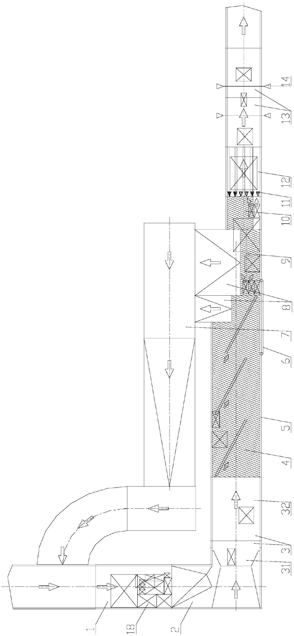
[0043] An automatic tally system, wherein a feeding belt conveyor (1), a special-shaped chute (2), a preliminary finishing belt unit (3), a side finishing machine (4), and a discharging conveyor are sequentially arranged along the conveying direction of the material (18). (9), a transverse separator (10), a longitudinal separator (12), and a flow control belt unit (13). The feeding belt conveyor (1) and the primary finishing belt unit (3) are vertically overlapped through the special-shaped chute (2); the guard plate (5) and the side vertical belt (6) are arranged on the right side of the side finishing machine (4). frame (41) side; the discharge chute inlet (81) is arranged at the output end of the side finishing machine (4), on the same side as the left frame (42) and the discharge roller (91) of the side finishing machine (4) ; The material return conveying unit (7) is connected to the discharge chute outlet (82) of the discharge chute (8), and finally the return material i...

Embodiment 2

[0045] On the basis of the aforementioned technical solutions, during specific implementation, the following features can also be included to form a technical solution to further achieve the purpose of the present invention:

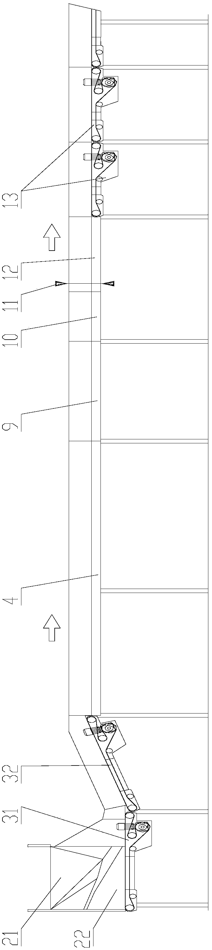
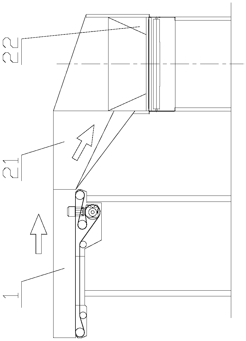
[0046] The special-shaped chute (2) includes two sections that are connected to each other and have a drop between each other and cause the material to flow to different chute I (21) and chute II (22). The outlet of the belt conveyor (1) is overlapped; the chute I (21) is provided with a plurality of sliding surfaces I (211), sliding surfaces II (212) and sliding surfaces III (213) with different angles along the flow direction from the inlet. , the end of each sliding surface is provided with a common sliding surface IV (214), the sliding surface IV (214) is connected to the chute II (22), and the outlet of the chute II (22) is connected to the initial finishing belt unit (3); The finishing belt unit (3) includes a flat-connected preliminary finishing b...

Embodiment 3

[0049] On the basis of the aforementioned technical solutions, during specific implementation, the following features can also be included to form a technical solution to further achieve the purpose of the present invention:

[0050] According to the flow detected by the flow detection device (14), the feeding belt conveyor (1) adjusts the speed or starts and stops the rhythm in real time, so as to control the feeding flow, balance the peaks and valleys of the flow, and prevent excessive materials (18) from entering the return conveying unit (7). );

[0051] For the profiled chute (2), see Figure 5 , including two sections of chute I (21) and chute II (22) that are connected to each other and have a drop between each other and cause the material to flow in different directions; preferably, chute I (21) and chute II (22) are horizontal The material flow direction in the projection direction is 90°. The material flow direction of the chute I (21) is the same as that of the fe...


PUM


Abstract

The invention relates to an automatic tally method capable of automatically sorting batched materials in the staggered, overlapped and stacked states into a single line arrangement on-line output way.The automatic tally method includes the steps that feeding is conducted; initial sorting is conducted, single line arrangement sorting is conducted; elimination sorting is conducted; transverse separation is conducted; longitudinal separation is conducted; the flow rate is detected to adjust the feeding speed or start-stop; and different speed differences are adopted to detect the material spacing. According to the automatic tally method, finished goods are automatically sorted.

Description

technical field [0001] The invention relates to an automatic tally system, in particular to an automatic tally system that automatically arranges batches of materials in staggered, overlapped and stacked states into single-line arrangement and online output, belonging to the technical field of logistics sorting. Background technique [0002] In the transshipment center, the common way of tally is: the express parcels concentrated in cages or sacks are placed in piles on the belt conveyor, and then manually separated one by one, and automatically transported to the automatic sorting system. Due to the large volume of express parcels, the labor intensity of personnel is extremely high. [0003] Patent CN 105102354 A provides a single-row conveyor, the main feature of which is that a belt or roller conveying downstream is arranged in the middle, and the conveyor belt or roller is vertically higher than the adjacent outer inclined and convergent drive rollers. The patent also d...

Claims


Application Information

Patent Timeline
IPC IPC(8): B65G47/22B65G47/30B65G47/88
CPCB65G47/22B65G47/30B65G47/88
Inventor 闵定勇张志英丁兴尚高海邹朝普刘强连小嫚胡建法王浩旭
Owner KUNMING KSEC LOGISTIC INFORMATION IND
Why Eureka
Try Eureka